Over the years, I’ve done the odd woodworking project, like building a guitar speaker cabinet or putting some shelves on the wall. I’ve used wood glue before, and I have (had) an ever-growing collection of all kinds of wood screws in my toolbox, mostly leftovers from previous small wood-related tasks. Up until a few months ago, I didn’t have any woodworking power tools, such as a circular saw or a router. I hope that suffices to describe my woodworking skill level, which I would summarize as: Can glue and screw wooden things together that other people have cut to size.
One issue that bothered me with all these previous simple projects was the imperfection resulting from poor measuring and marking, as well as poor planning. I would sometimes work out the dimensions using only a folding rule (“Zollstock”), a pencil, and paper. Other times, I would use a vector drawing tool on my computer. You can find examples of some of my previous projects in these blog posts:
Obviously, I successfully built these things, but I was rarely satisfied with the results. I had to accept the imperfections and sometimes force parts into place to make them fit where they were supposed to go.
Getting inspired by Youtube
A couple of months ago, I wanted to upgrade my IKEA standing desk to something sturdier and with built-in presets. Since I got a nice tabletop for free from a nearby office that was closing down, I only needed a frame. Once the frame arrived, I had to figure out where to drill the holes in the tabletop to mount it properly. For that, I started looking for tutorials on how to drill straight holes into wood, which led me to a German YouTube channel by Jonas Winkler and down the woodworking rabbit hole.
The creator of the YouTube channel is neither your typical nor your traditional carpenter, and he is certainly not your typical German YouTuber. The way he looks and talks is unusual, but for me, that is a welcome contrast to the otherwise rather conventional and often boring German DIY content. On top of that, his humor made me chuckle many times, which is definitely a plus.
To keep this part of the story short, let’s just say that I subsequently managed to drill the holes and mount the tabletop, and I’m now happily typing this blog post at my new desk. Success!
But of course, the YouTube algorithm kept feeding me more videos from this newly discovered channel every day. And … I did the research: I exported my YouTube watch history, processed and searched the data, and found that I watched the first video on 2026-04-14. By 2026-07-16, I had watched … 395 videos from this channel alone, ranging from gear reviews to practical tutorials. Add another 87 videos from the other German channel, Let’s Bastel, and you get an idea of what I mean by “draining” a YouTube channel.
What I got out of this was an understanding of which tools these guys used to realize their projects, as well as which techniques they repeatedly relied on to achieve certain results. For example, I learned how they glued wood together, how they used circular saws, why both preferred plunge saws over conventional handheld circular saws, which tools they used for measuring and marking, and what not to do—both for safety and to avoid wasting money.
After this ingress of new information I had my first project in mind to try out some of the things I’ve learned. I was thinking about doing it like I always do, with pencil and paper or a vector drawing tool … or maybe this would be the perfect time for doing it with a CAD tool?
CAD: First Contact
I knew that CAD tools could be useful for woodworking and that they offered benefits such as technical drawings, exploded views, parts lists, and cut lists, which could in turn be fed into cut-optimization software for plywood sheets.
Long before I chose programming as a profession, I worked as a graphic designer, so I was very familiar with all the usual tools of the trade, such as Photoshop, FreeHand, Illustrator, and so on. However, I had never seriously used any 3D software, and I had never touched a proper CAD program at all.
After a brief search for a beginner-friendly CAD tool, I ended up trying Shapr3D. While it worked well enough for my first project, a Sortimo shelf, I quickly became annoyed by the limitations of the free version. To be fair, Shapr3D is designed to work on an iPad, so the focus is clearly on usability and the user experience on touch devices. I’d say they’ve done a great job in that regard.
I had heard of Onshape before, mostly through Youtube again and the many creators using it like Tom Stanton, rctestflight, Peter Sripol and many more. I created an account and was immediately intimidated as it looked far more complex than Shaper3D but with the help of youtube tutorials and $LLM guidance I quickly recreated my “design”. Compared to Shaper3D, the free version of Onshape lets you import and export, create parts and cut lists and I was able to use one of the cut optimizer websites (Cutlist Evo) to figure out a reasonable sheet size for the plywood which I would order right away.
A week later, the shelf was complete, and it was the most fun I had ever had building something out of wood. I achieved a level of precision I had never managed before, with the largest deviation in the entire assembly being just 0.5 mm. It was bliss to be able to refer back to my technical drawings and their precise measurements whenever needed. It was clear that this was only the beginning.
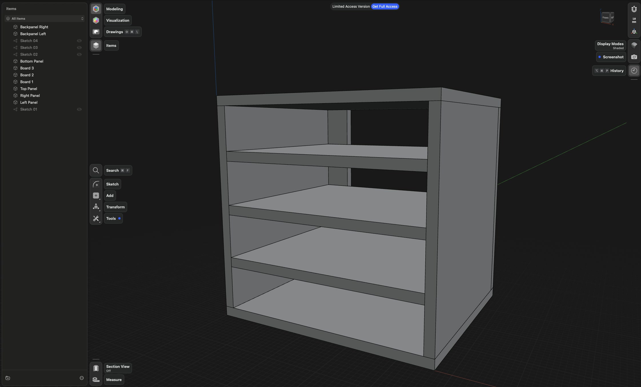
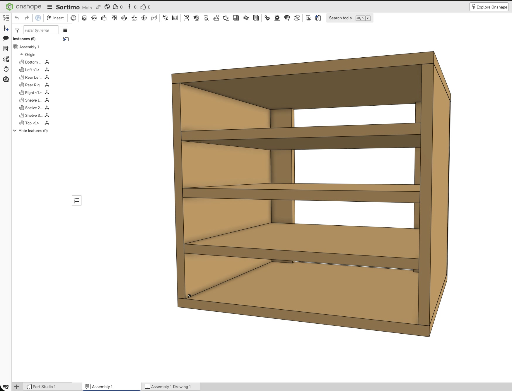

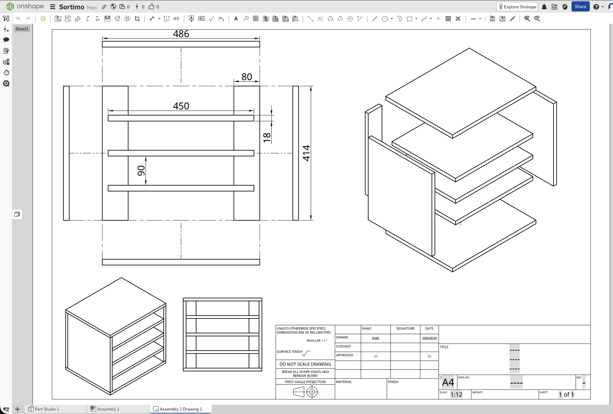
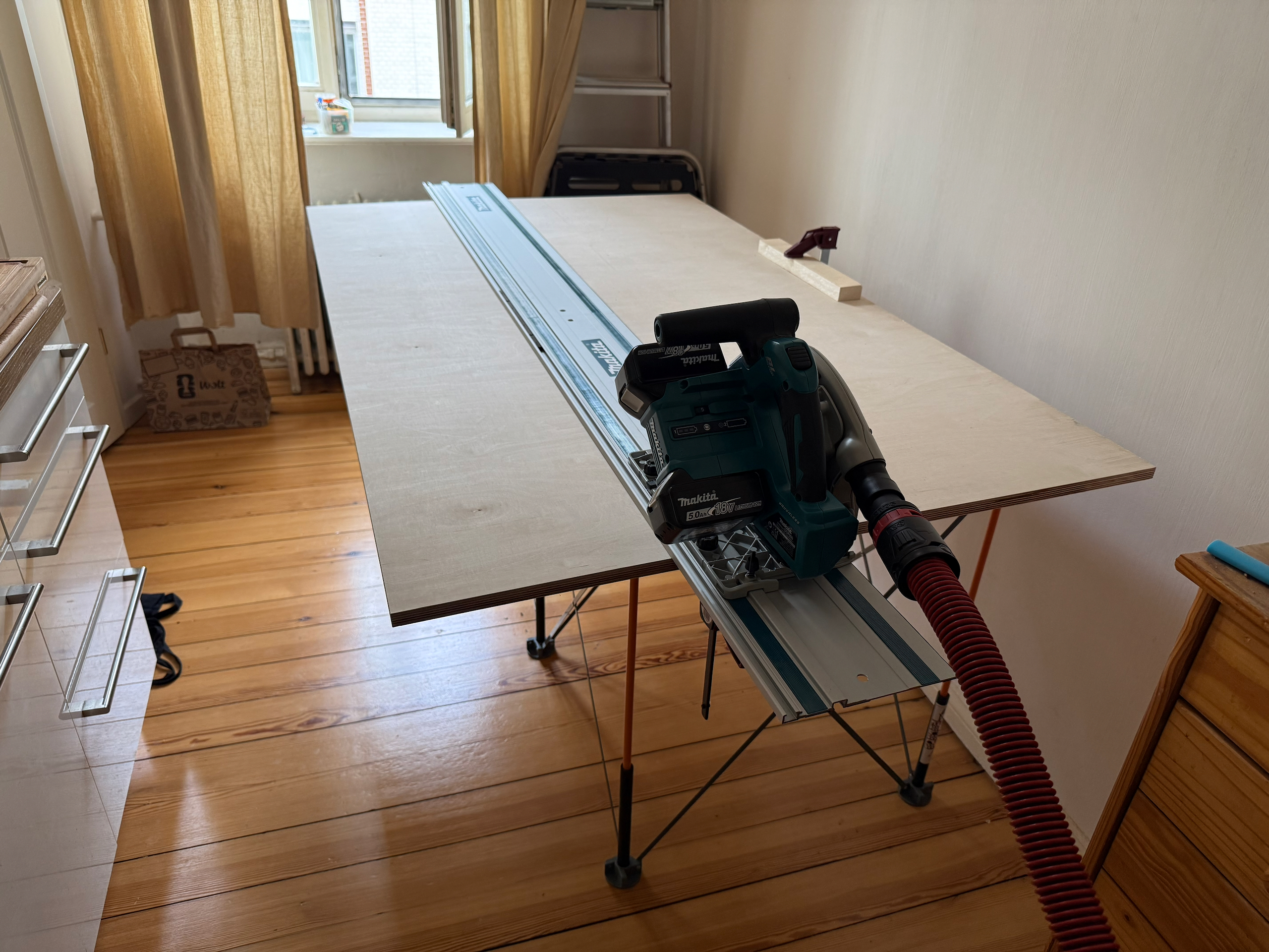
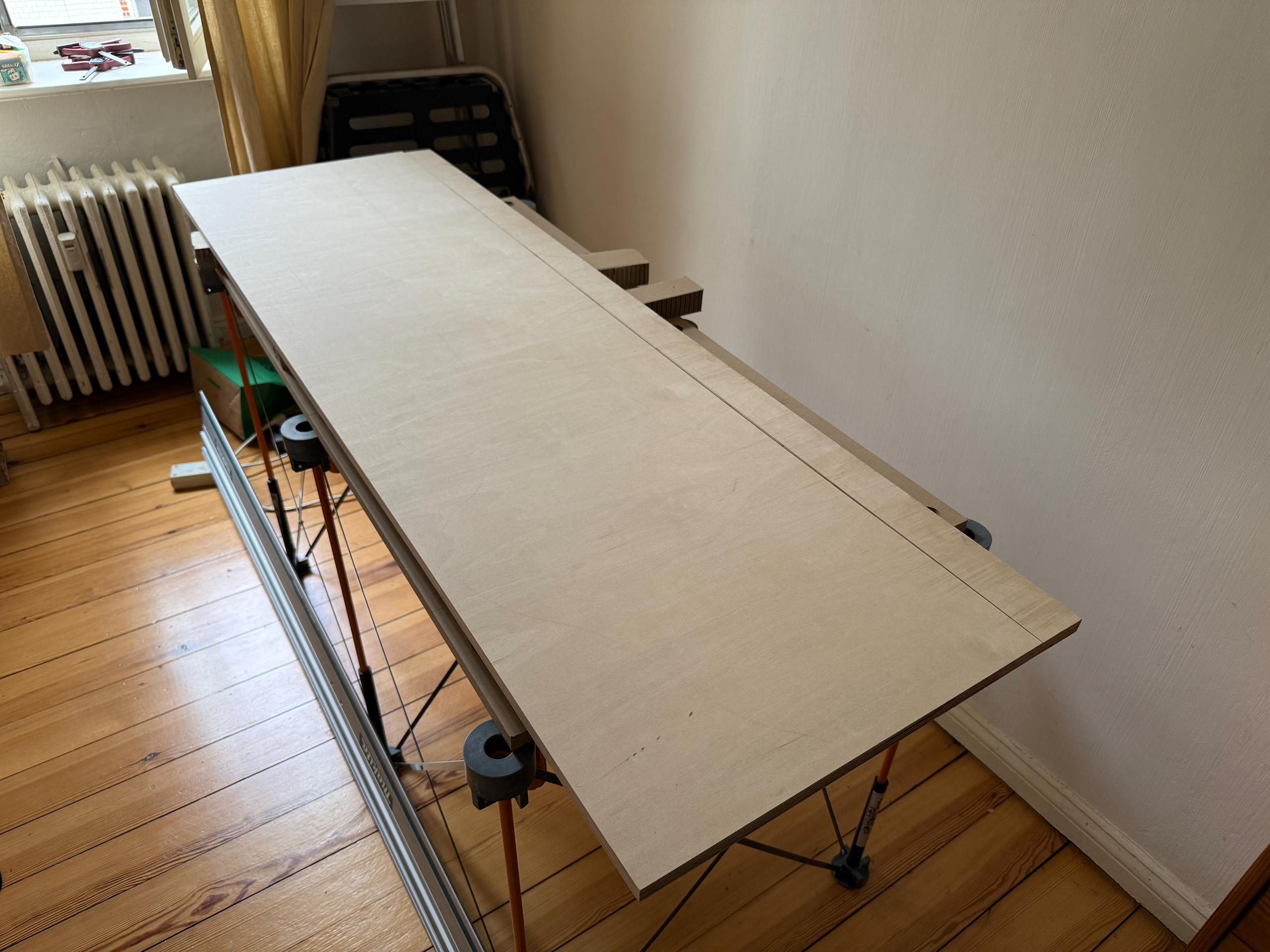
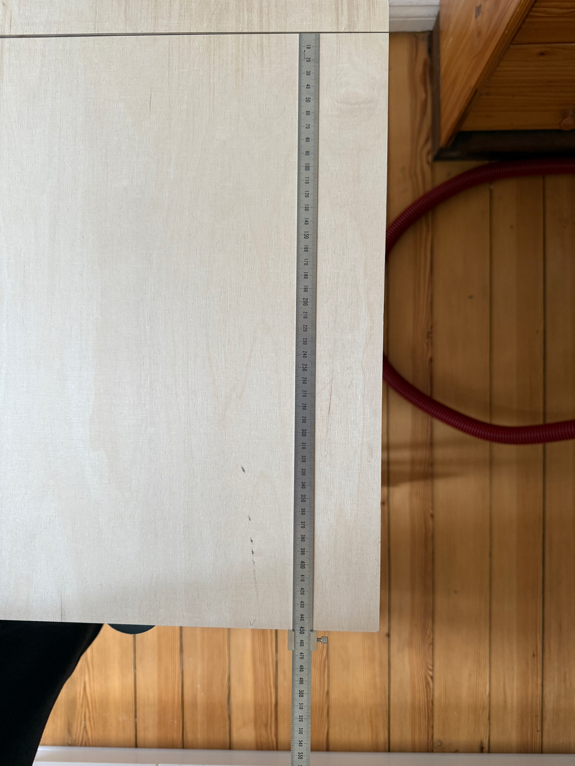
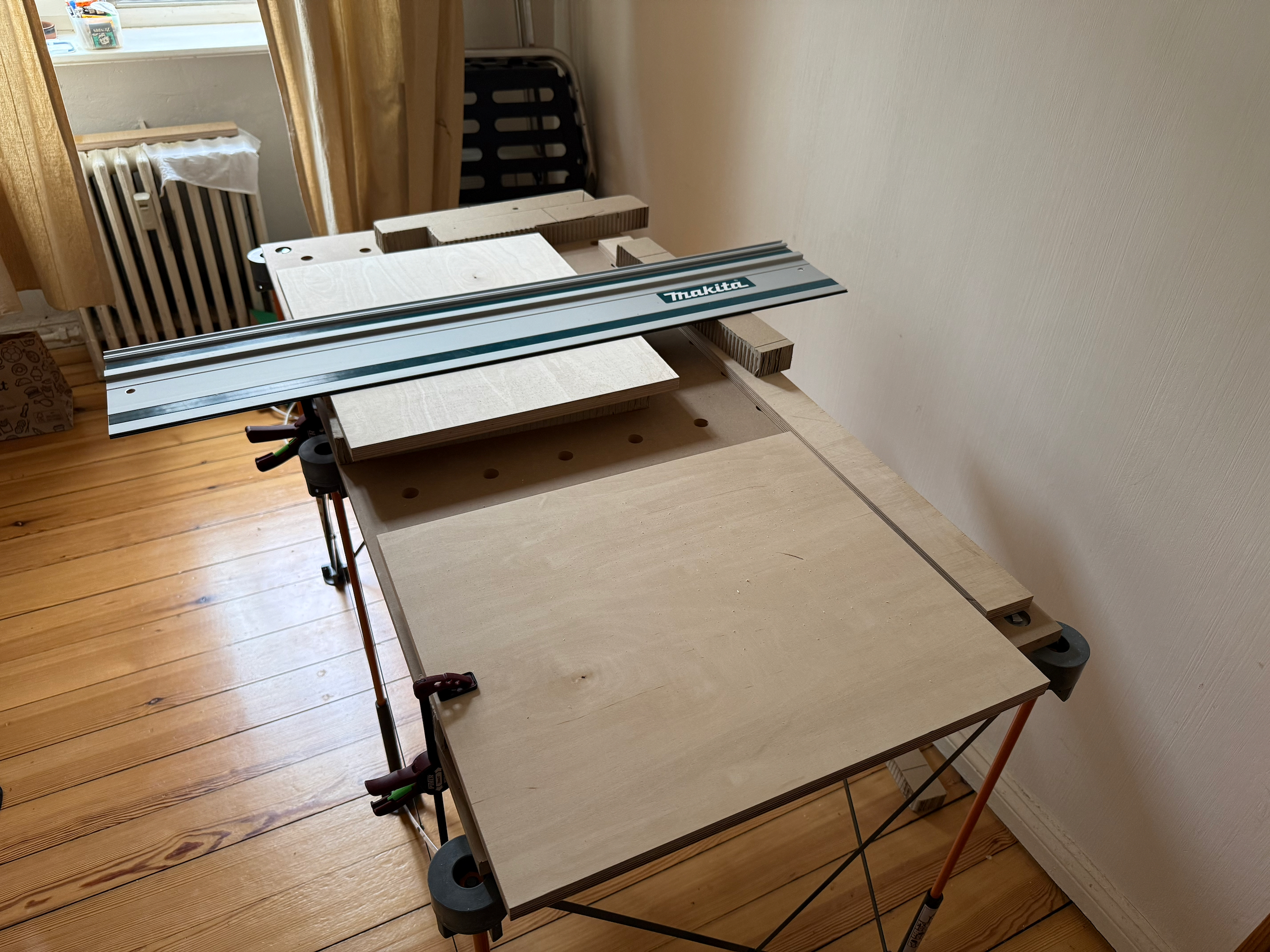
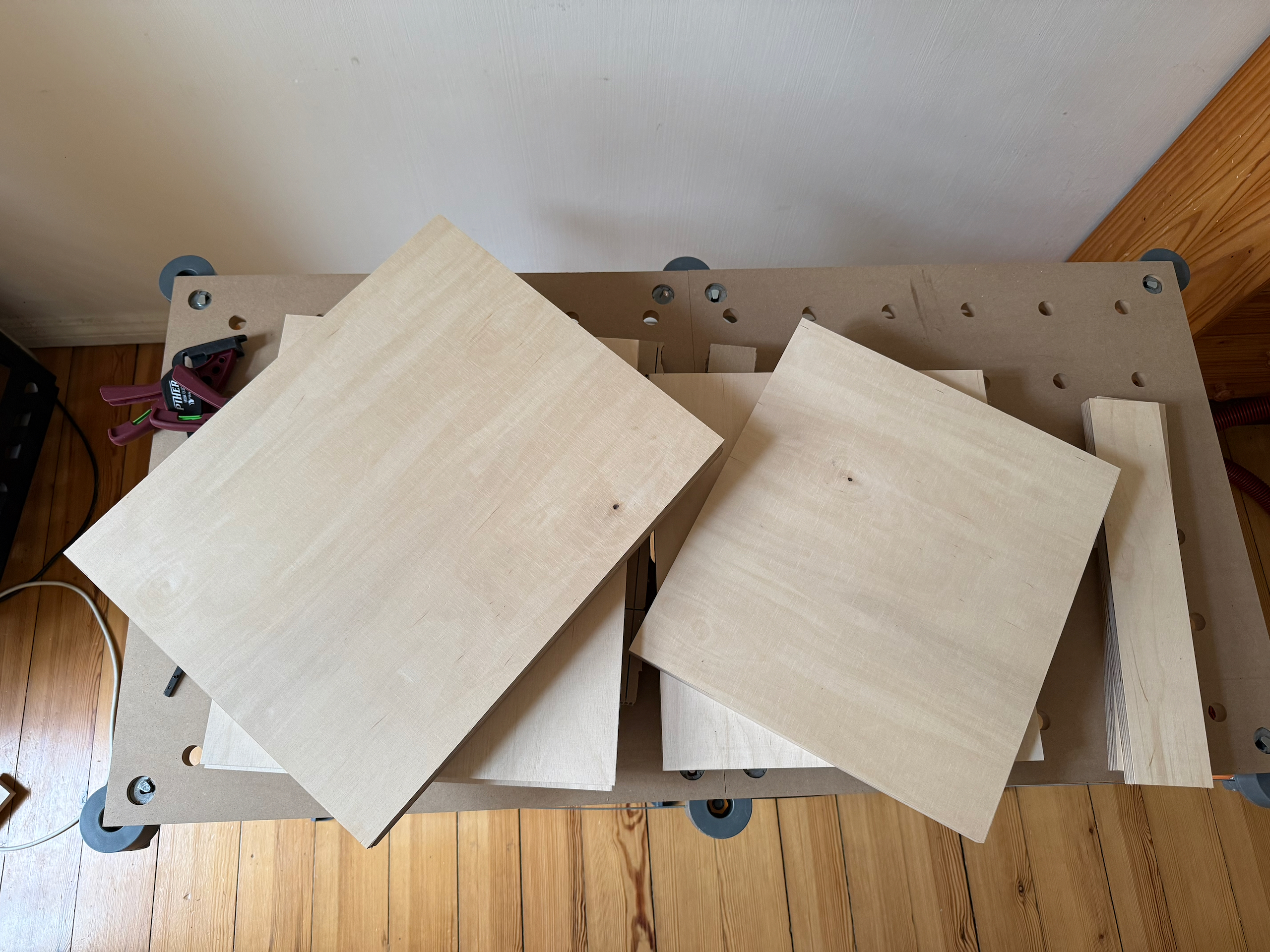
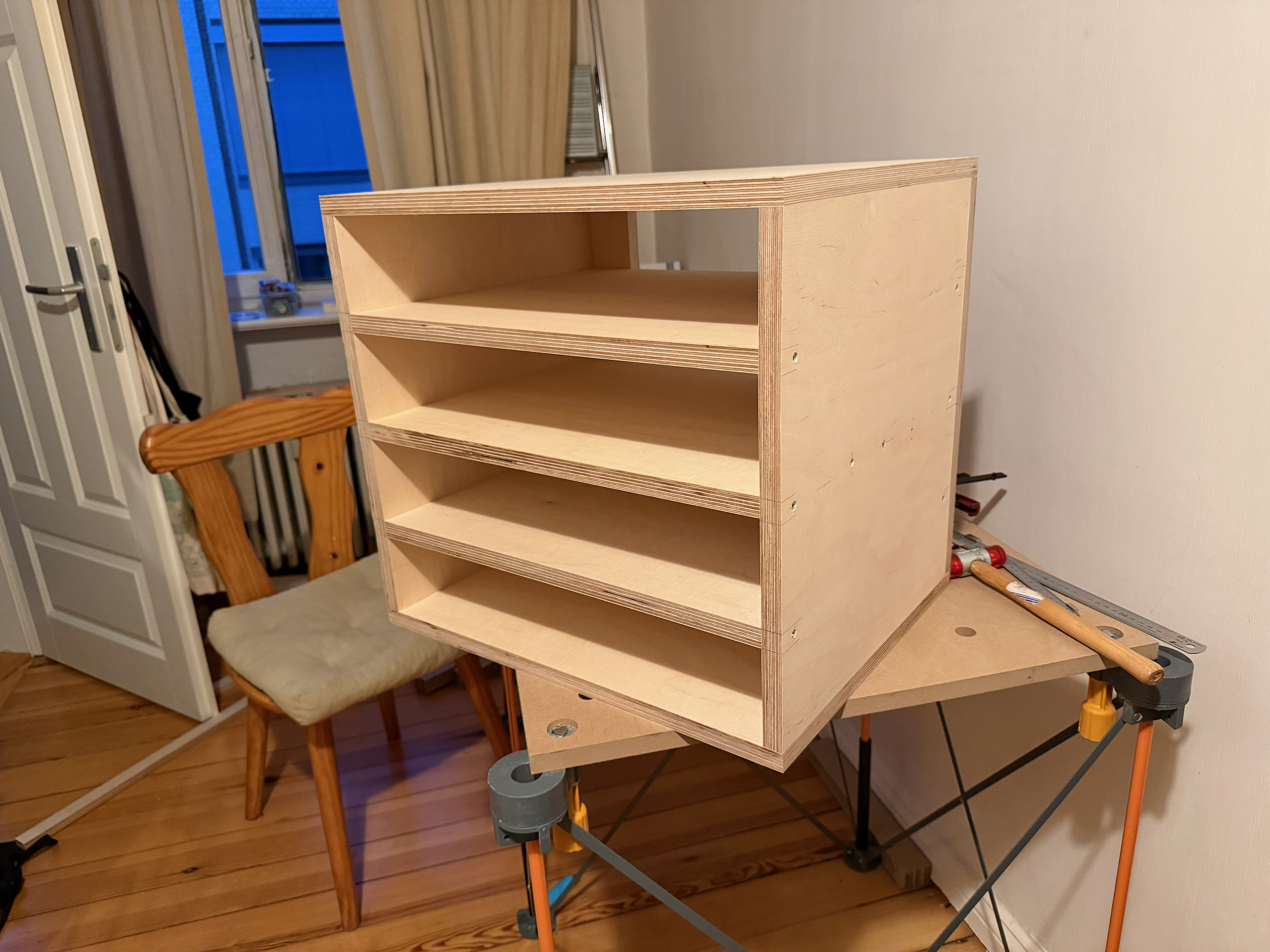
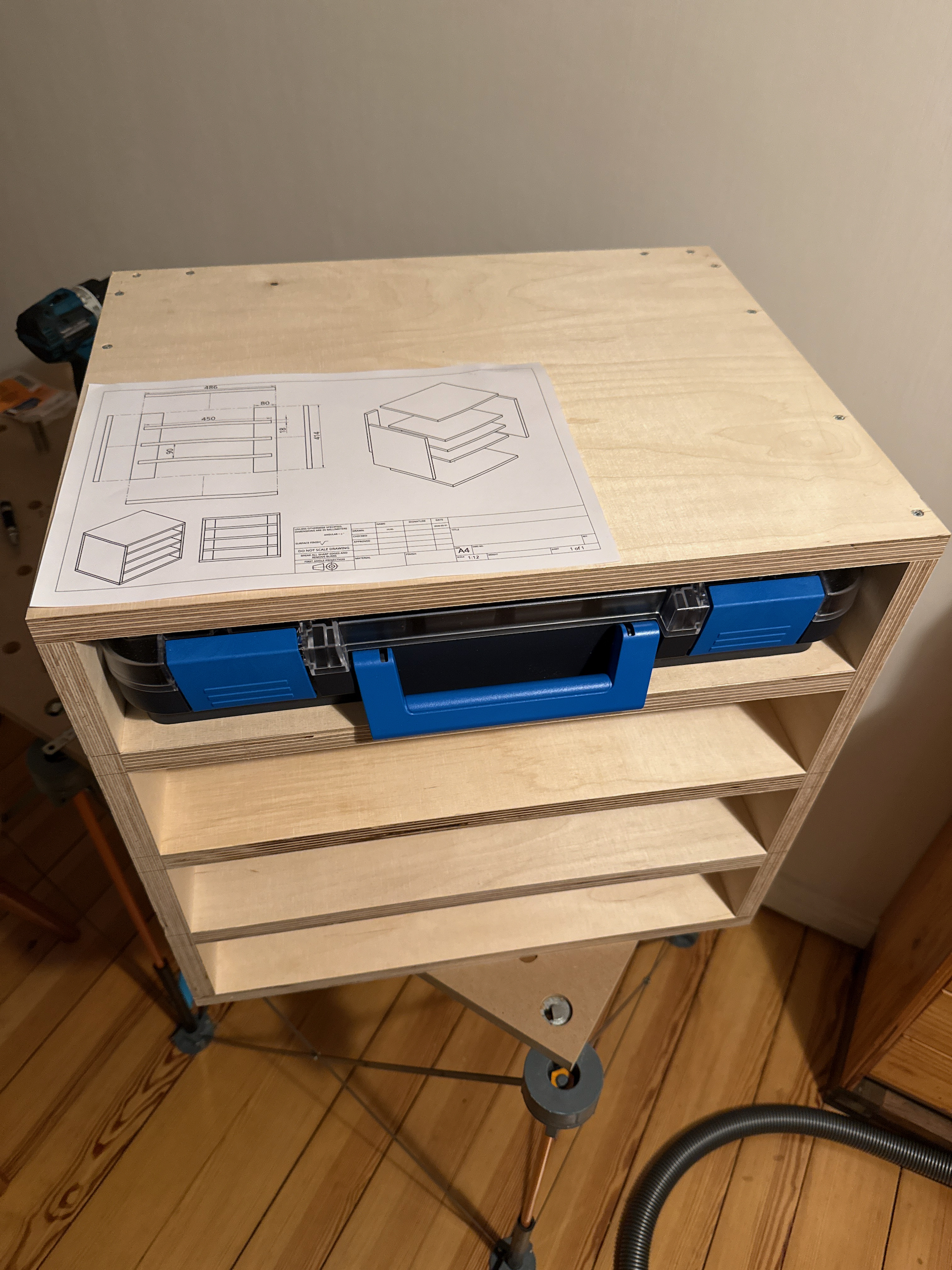
Sidenote: Yes, I cut the wood in my kitchen with a plunge saw. With the vacuum cleaner attached, I had minimal saw dust to deal with.
The next project: Polychrome
A few weeks after my first successful conversion from CAD to reality, another project snuck up on me when my partner mentioned something she was working on: some kind of light installation for a festival with an interactive element. The interaction was facilitated by tiny radar sensors that were meant to hang 5 m above the ground from six arms, each 3 m long and angled upwards at precisely 15°. The team was unsure how to build this out of wood using simple tools, as the budget was somewhat limited. Additionally, it needed to be stable and weatherproof enough to withstand wind and rain. The installation would also eventually undergo some form of safety inspection.
Fortunately, I had a long train ride coming up, and during the first six-hour leg, I decided to load up Onshape and try to come up with a design that could work. I had already learned a bunch of things the last time around, but I still had to learn a whole lot more, especially how to keep the design and its parts flexible, since the final dimensions would have to be determined later based on the available wood.
Again, $LLM was extremely helpful in explaining Onshape’s features and how to use them. Without it, I wouldn’t have been able to complete the first draft in six hours. This time, I designed each part separately, added custom mate connectors, and created subassemblies before putting everything together in the final assembly.
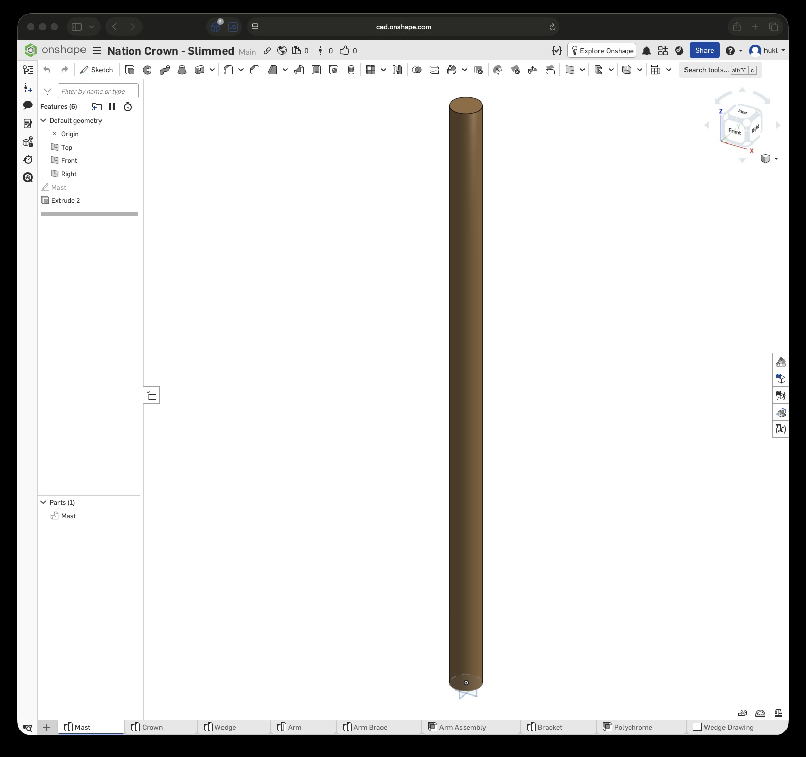
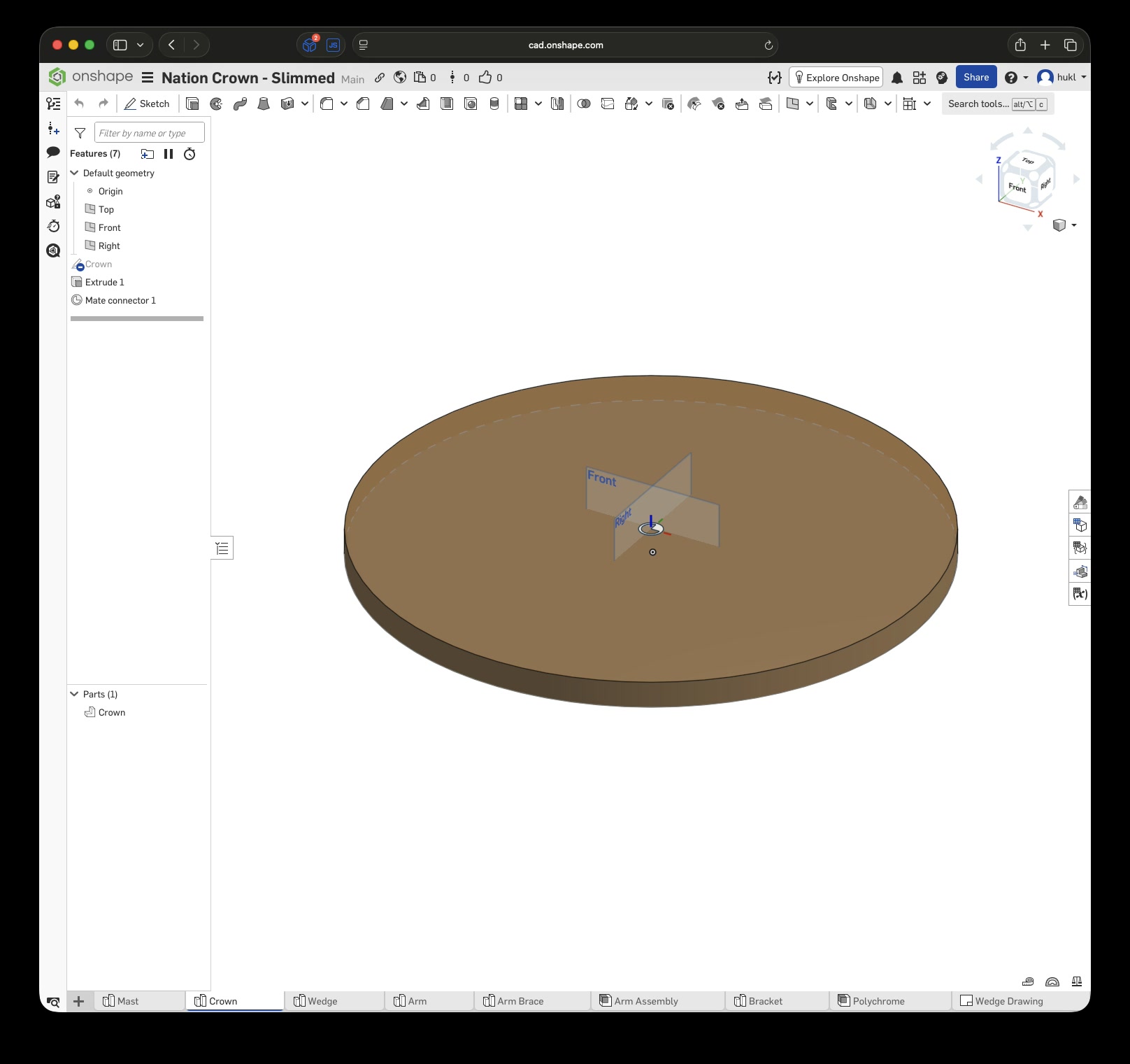
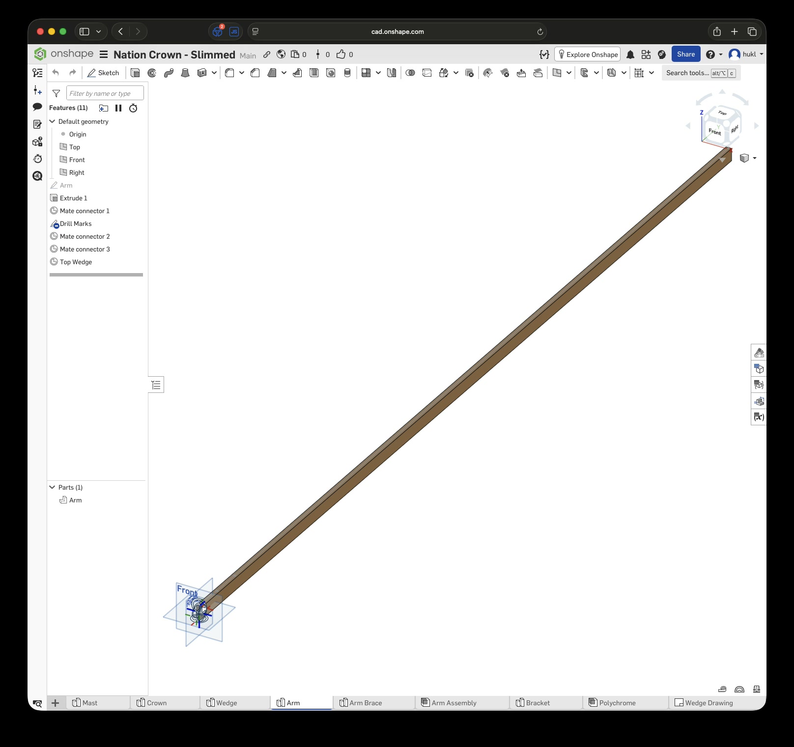
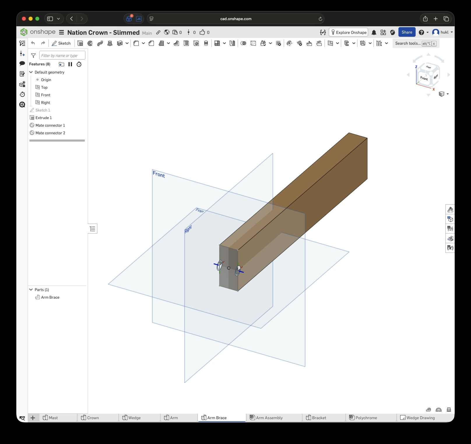
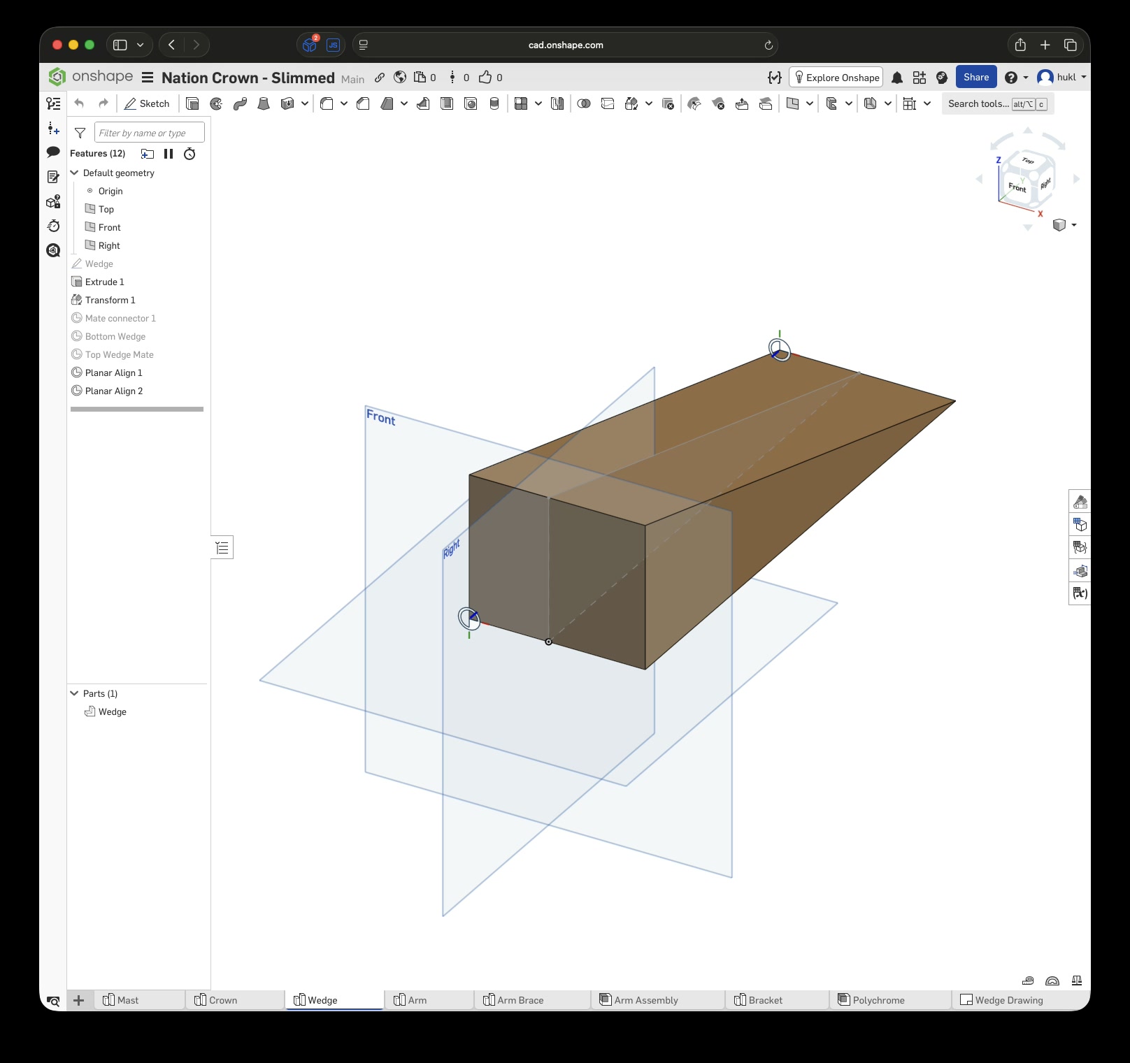
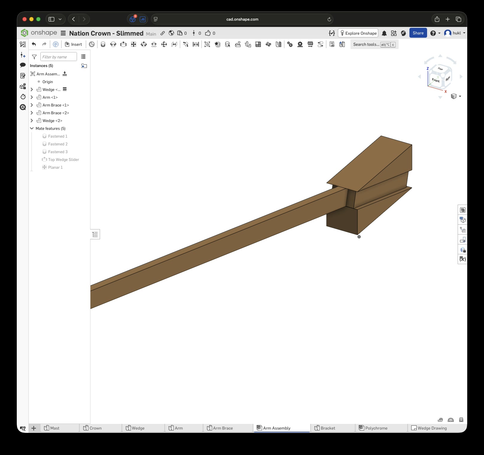
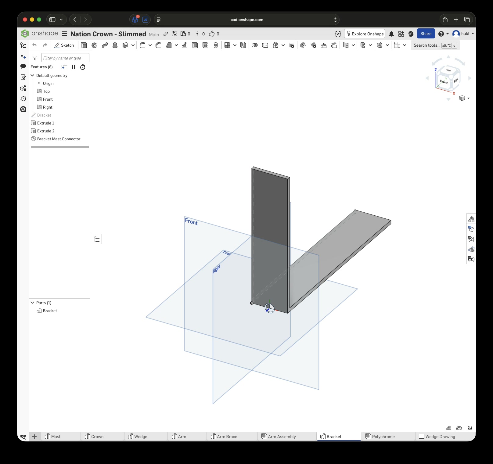
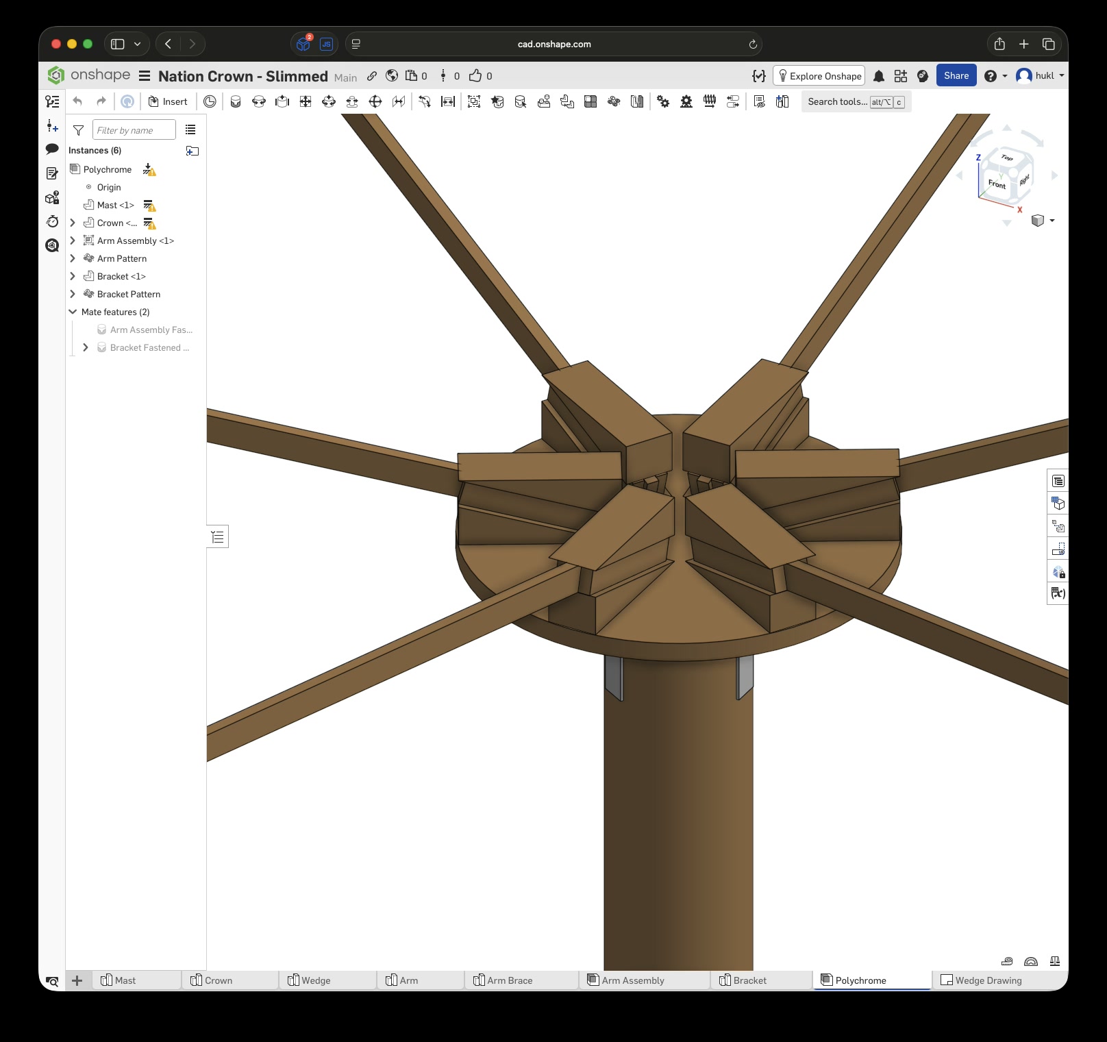
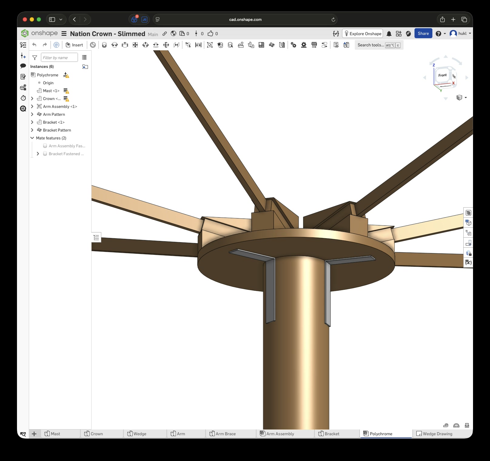
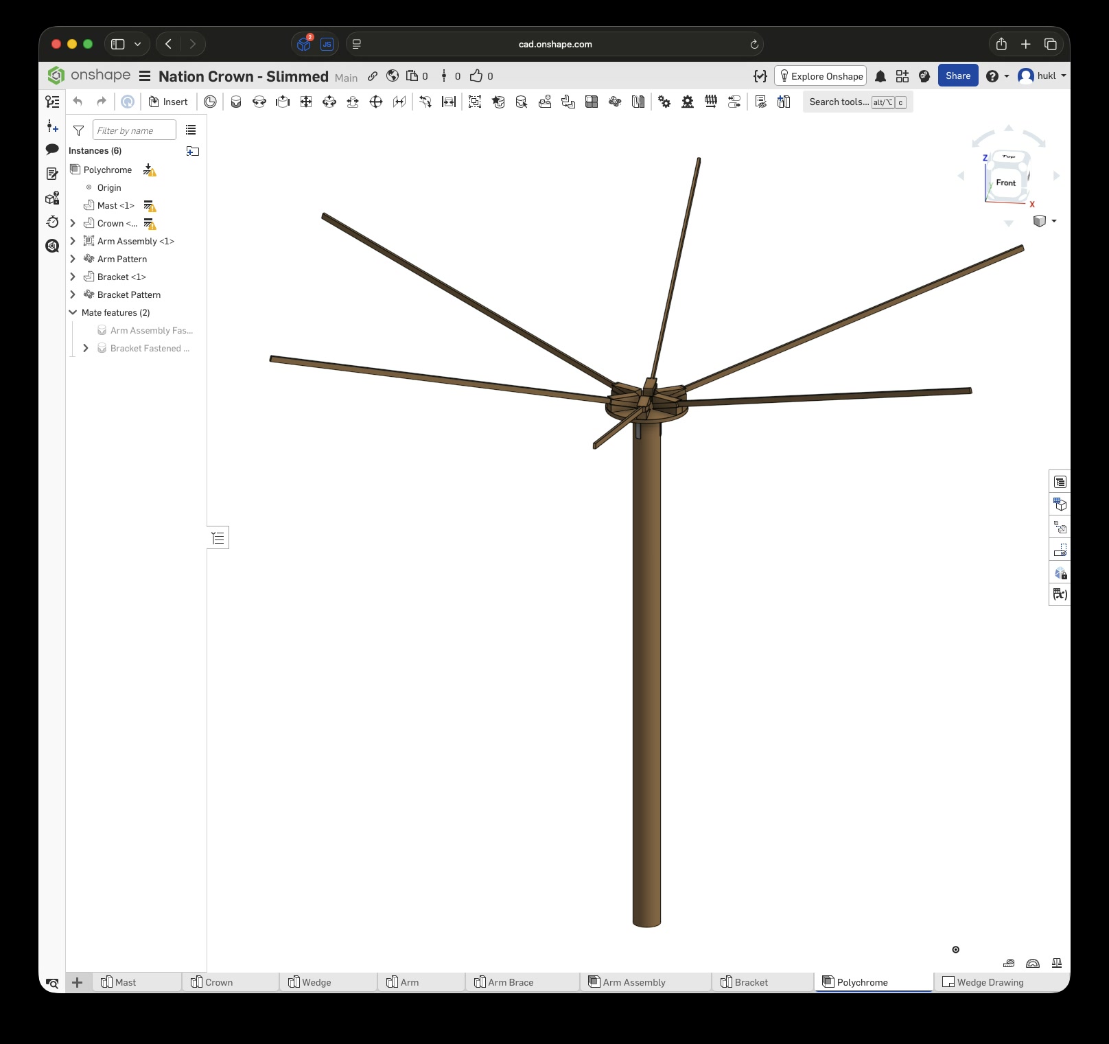
Click this link to view the CAD model yourself without an account. With an account you can copy and modify it. Just to be clear, I have no affiliation with Onshape – I just really enjoy this tool.
7 Days to make it real
A few weeks later, it was time to meet up and shop for some wood. Fortunately, we found a round disc with the perfect proportions, originally intended as a tabletop. Suitable wood for the arms followed shortly afterwards.
The mast was going to be provided by the festival, although its exact dimensions were not yet known. At that point, we also still had no clear idea what kind of wood to use for the wedges. I had a bunch of tools, but nothing that could cut them easily. Luckily, the festival had a dedicated woodworking crew with a modest workshop setup, including a proper table saw and miter saw. We therefore postponed choosing the wood for the wedges until we had spoken to them. If they lacked the appropriate tools, we would have to construct the wedges from several thinner layers instead.
Two weeks before the actual event, I packed up most of my tools and hauled them to the site. I was relieved to learn that the festival’s woodworking crew would indeed be able to cut the wedges to my specifications, and they were delighted when I handed them a technical drawing containing all the relevant measurements.
Sadly, I was unable to stick around and watch them make the cuts, but I assume they used their table saw with some kind of jig. Since my plunge saw can only cut about 5 cm deep with the guide rail attached, cutting the wedges to specification would have been quite a project in itself.
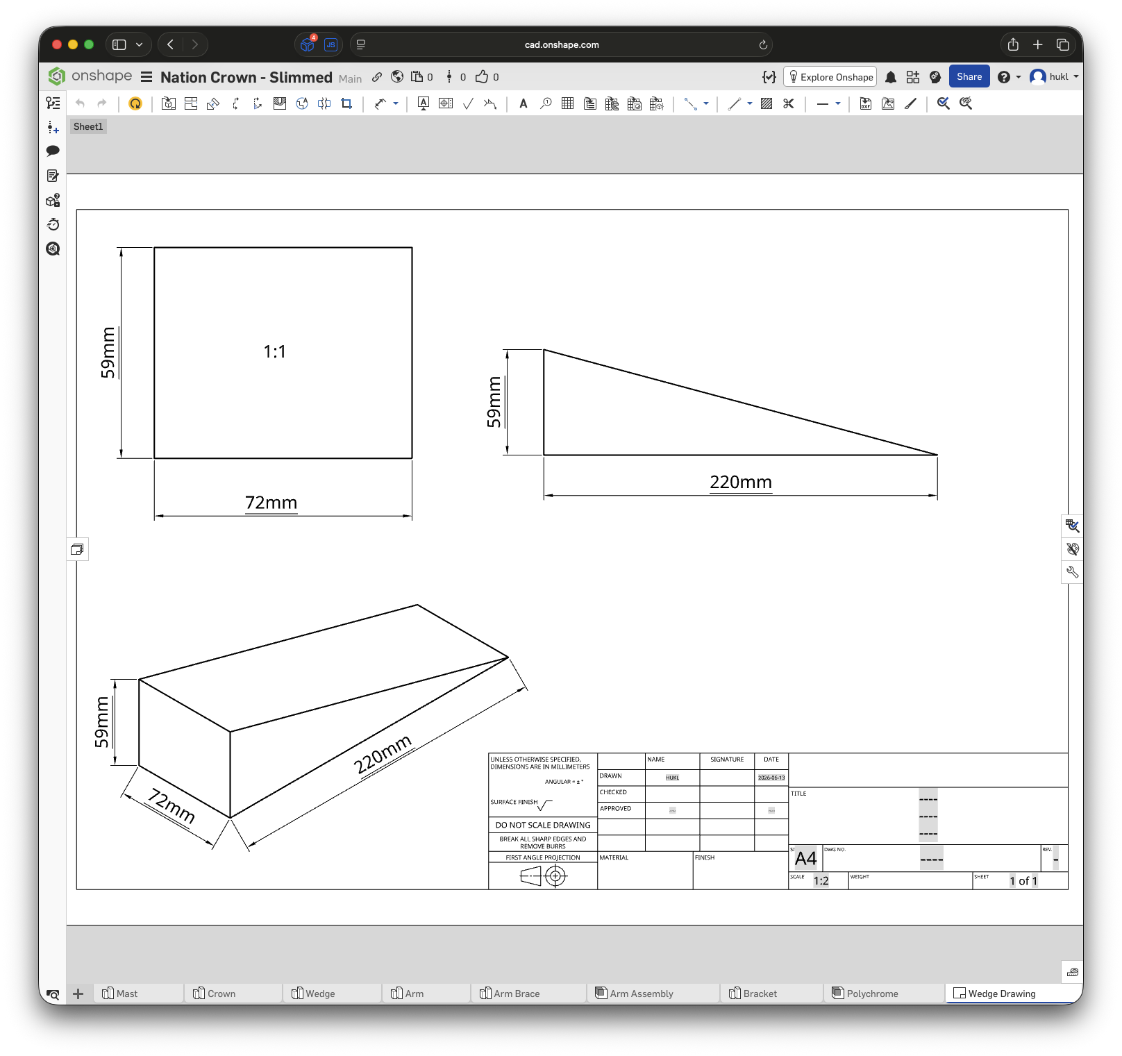
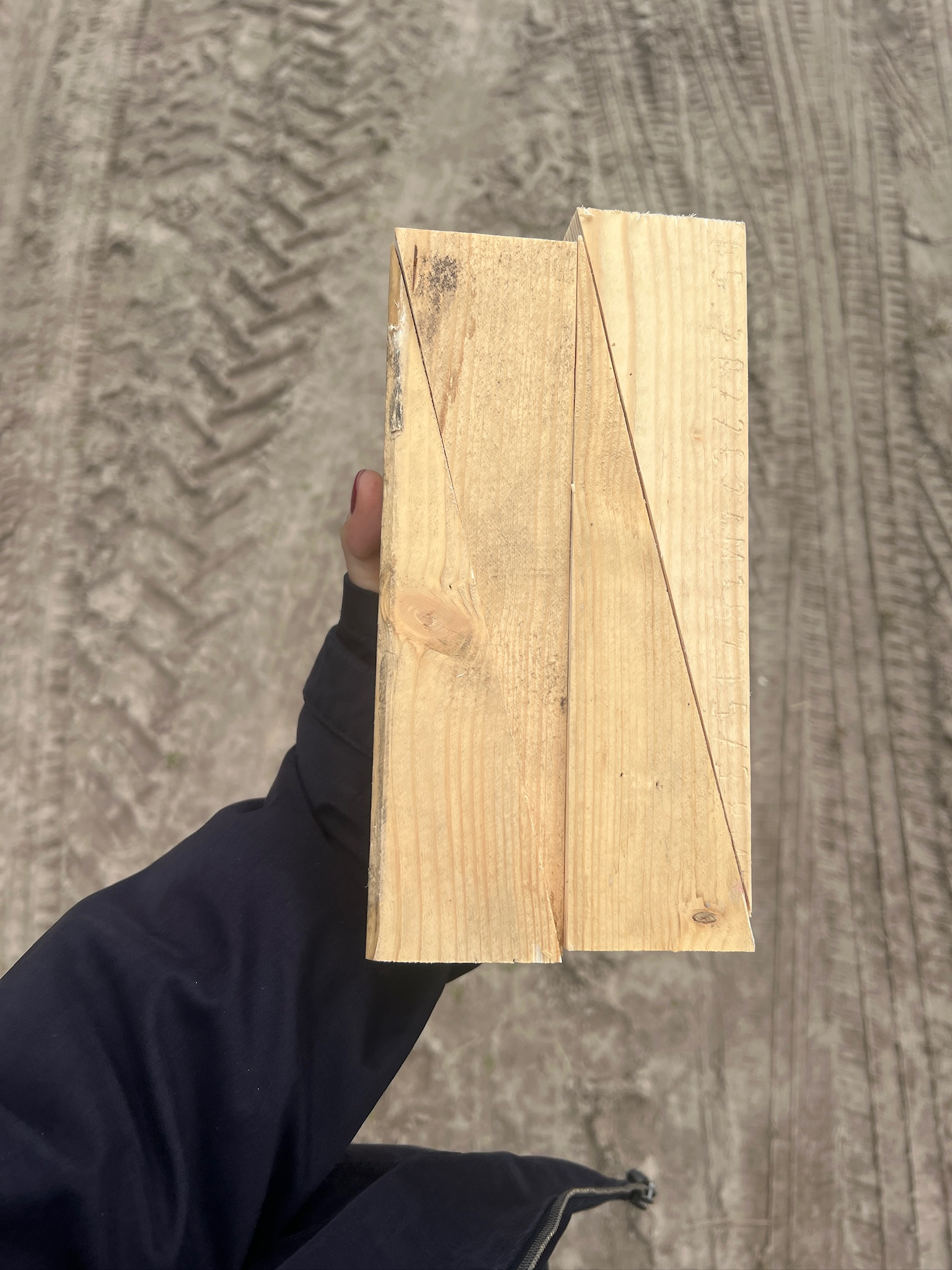
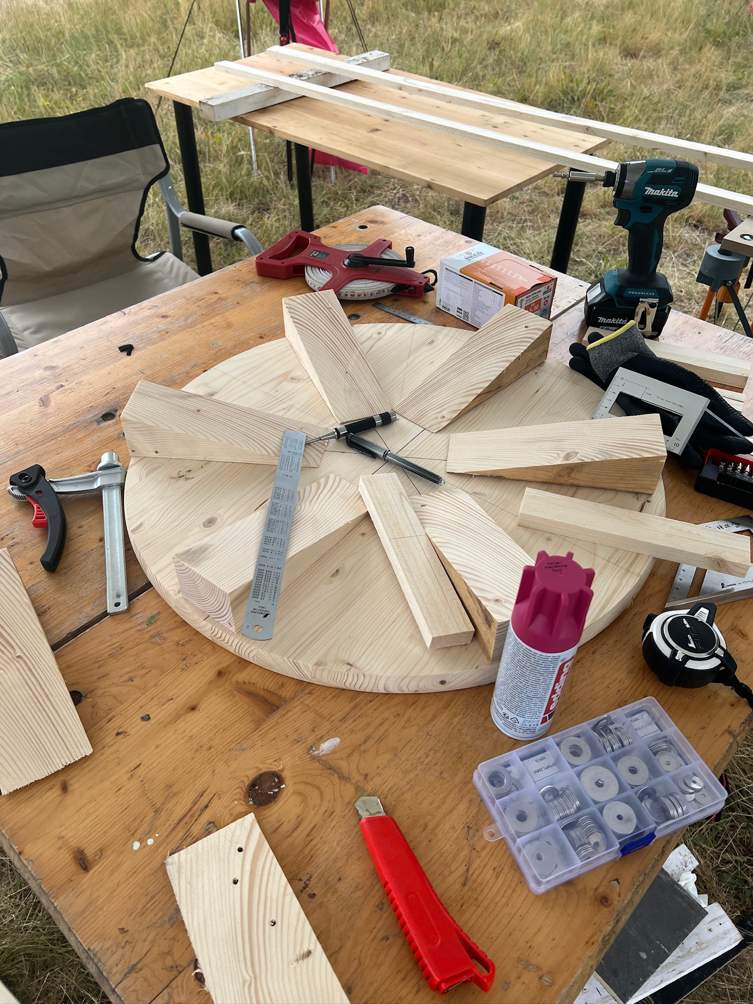
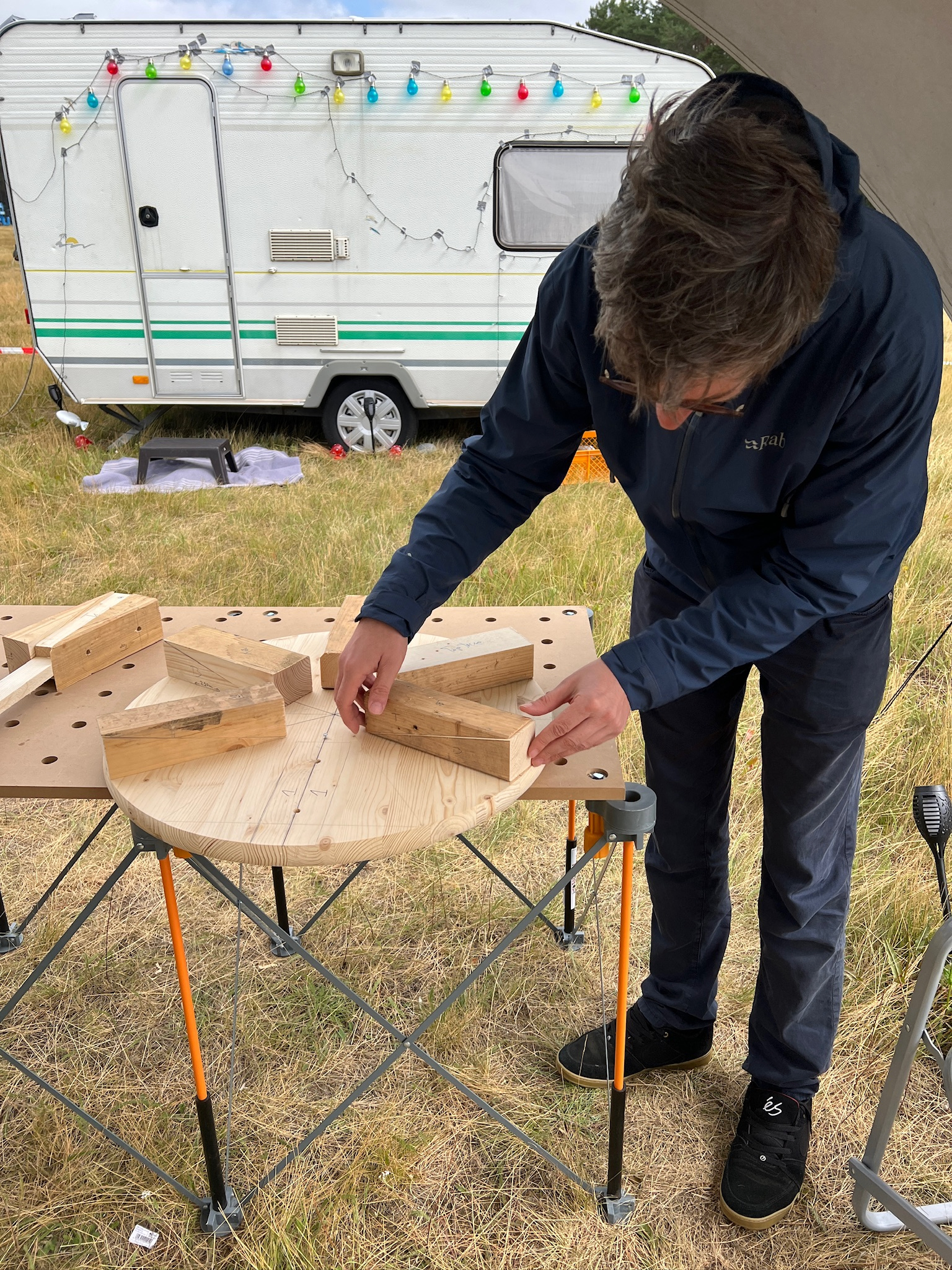
Similarly, we were quite lucky to find a tabletop with almost exactly the same dimensions as the one I had used in the CAD design. Otherwise, I would either have made a hexagonal “crown” base plate from thick plywood or attempted to cut a perfect circle with my router.
Especially during the early phase of gathering materials and filling in the unknowns about where and how we would obtain certain parts, it was incredibly useful that I had put in the time in CAD to make all the parts connect at the correct pivot or center points. This allowed us to quickly adjust the dimensions of individual parts without having to reassemble the entire design. Here is a quick demo video showing exactly that:
After three days on site and a few trips to the local “Baumarkt” ie. the home improvement store, we had all the parts and tools needed for the actual assembly. The one thing still missing was a wood drill bit long enough to drill through the entire base–wedge–arm–wedge assembly, so I could be sure that the metal bolts would pass through all of it smoothly.
The bolts, nuts, washers, and fasteners were only bought once we were certain of the final dimensions. Although I had planned to use M8 bolts from the start, the exact bolt length and the types of washers and fasteners we would need remained undecided until quite late in the process.
The decision to add a top wedge also came quite late. Initially, I thought the bolts, nuts, and washers would work fine even without parallel surfaces to bear against. However, once we had the wedges and I tried clamping everything together, it became apparent how useful those parallel surfaces would be.
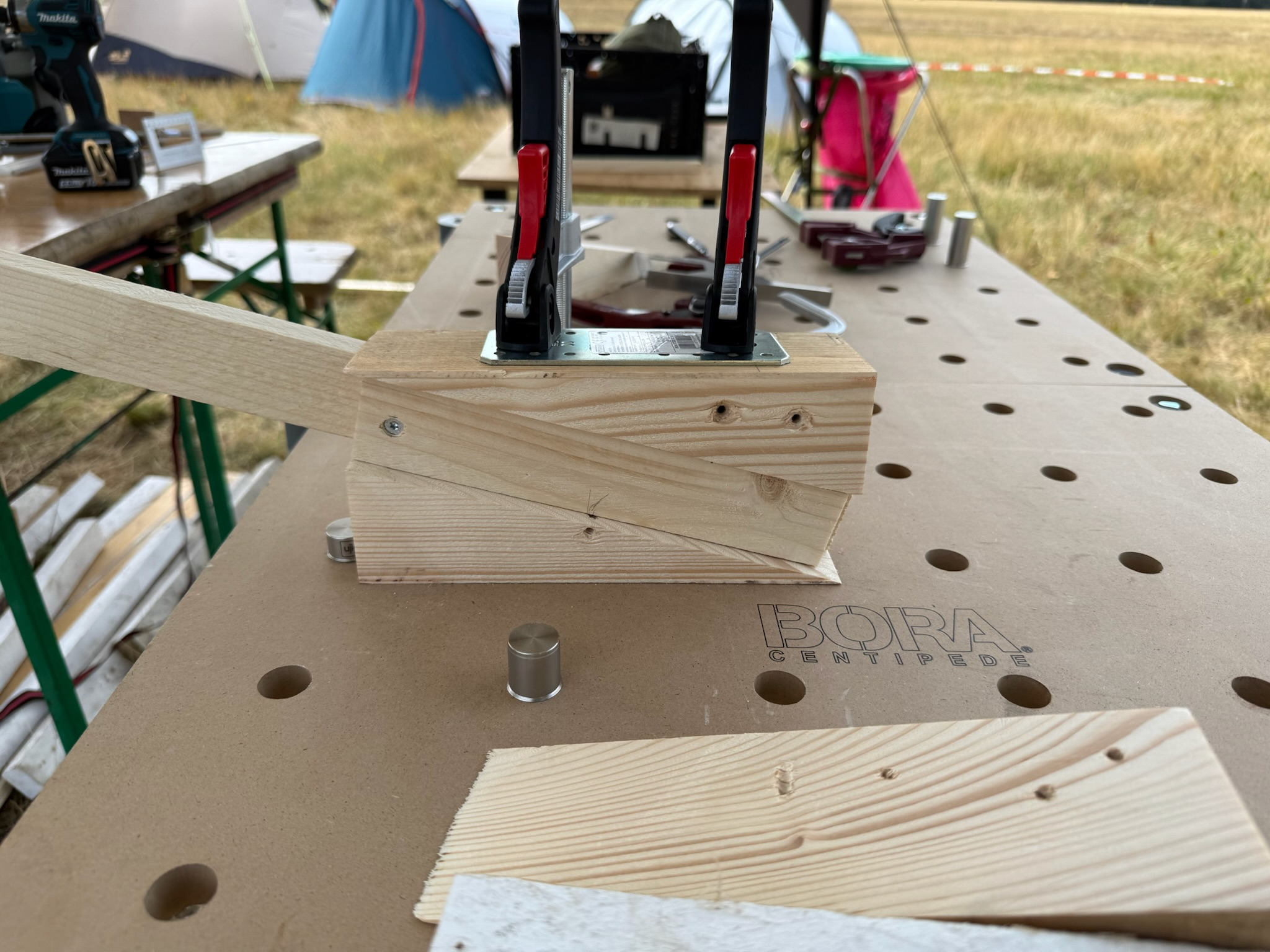
I went back to the on-site wood workshop and asked for a few more wedges, which they cut that same day. Finally, everything was ready for the preassembly of the arms, wedges, and base plate. I had to mark and number each arm and then do my best to drill straight holes through the entire clamped-together assembly. Getting everything into place, measuring, aligning, and clamping it took up most of the time on this project, but it was worth it.
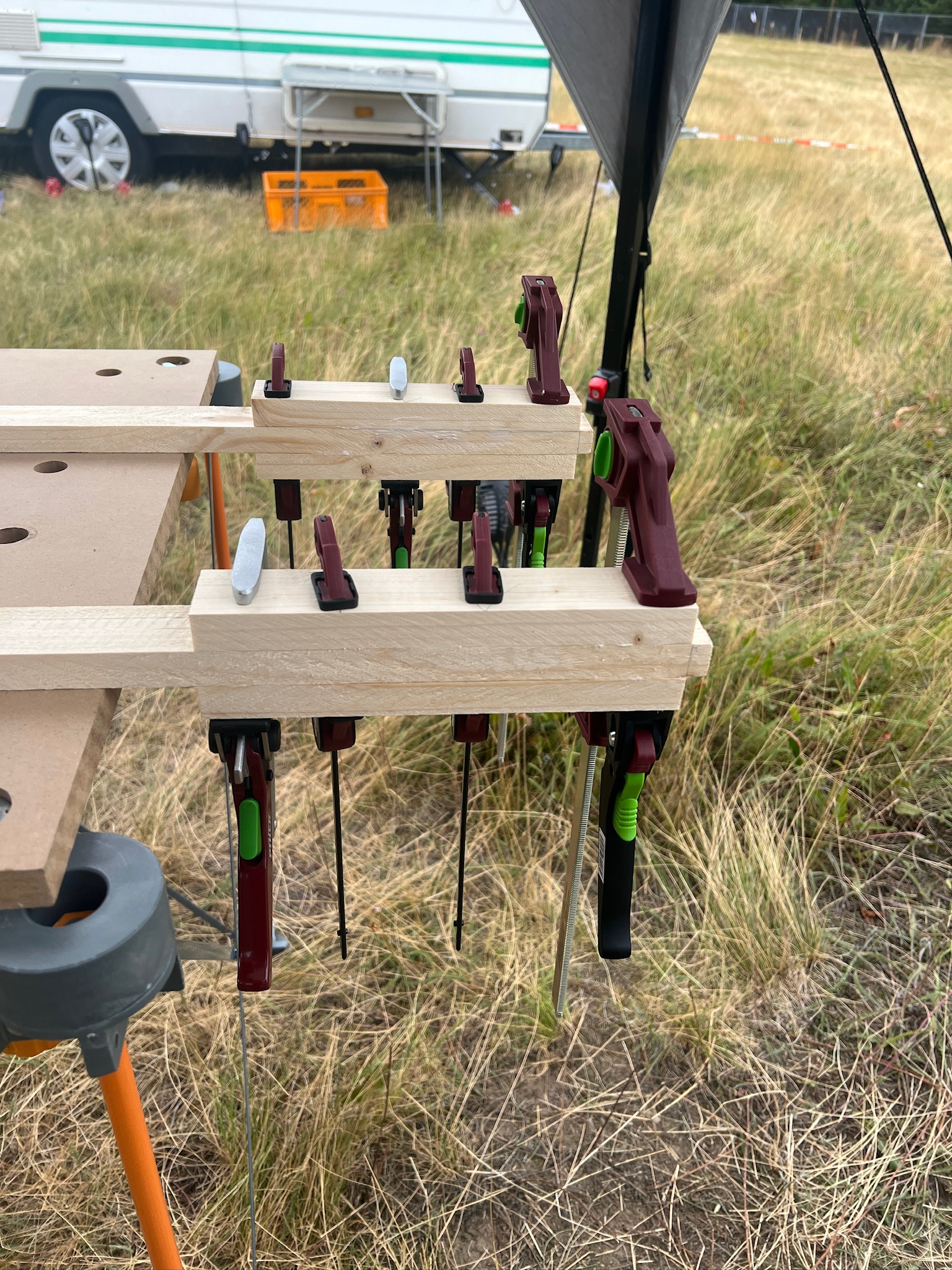
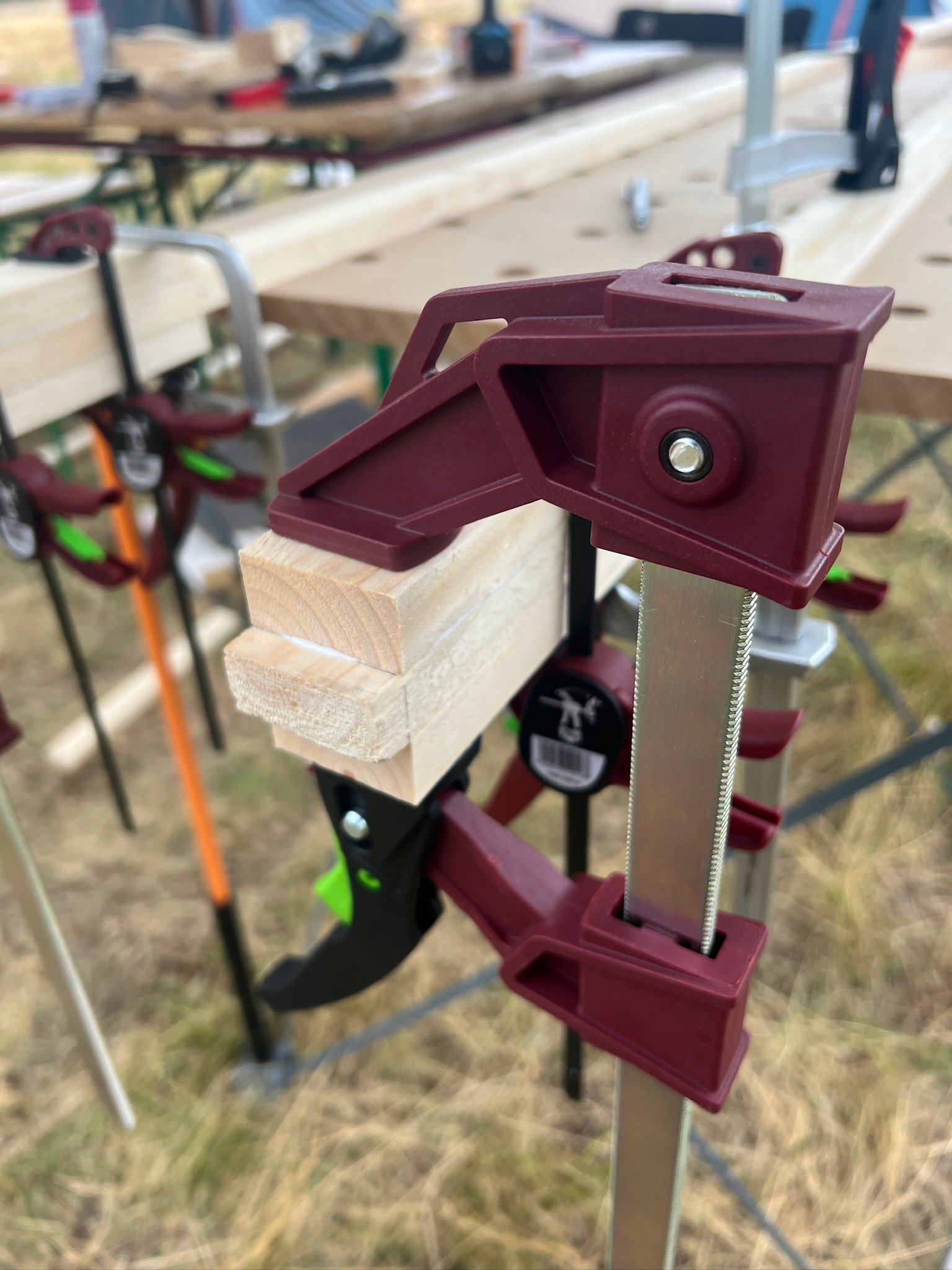
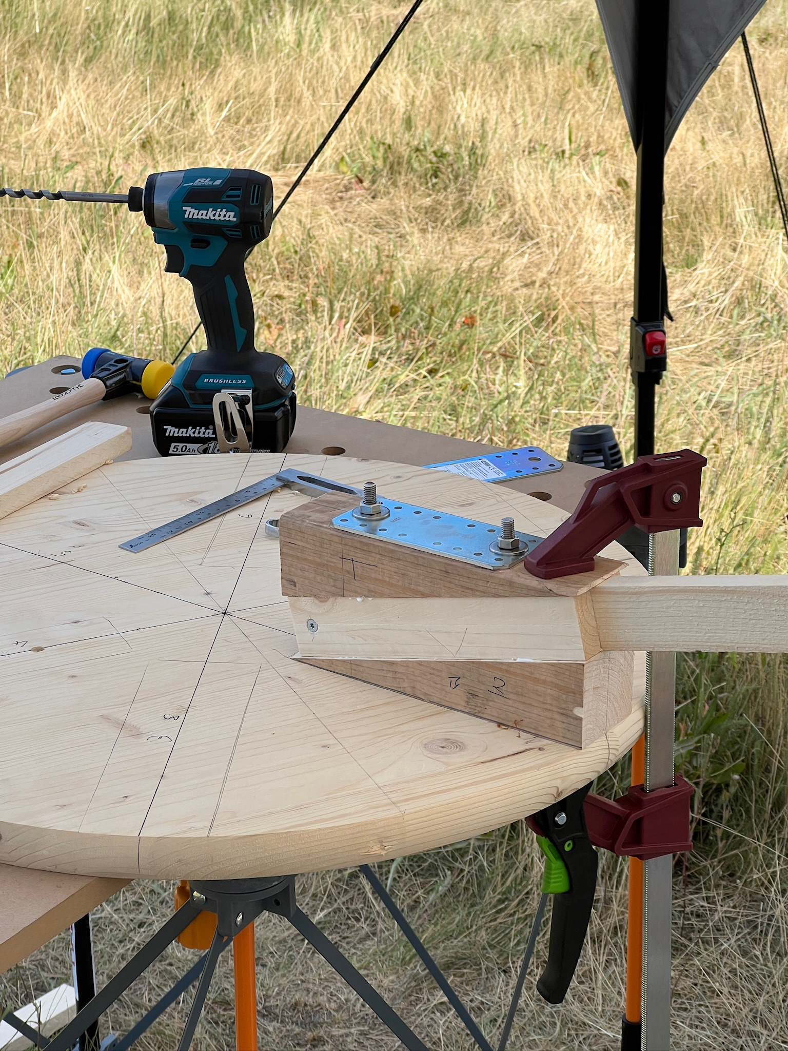
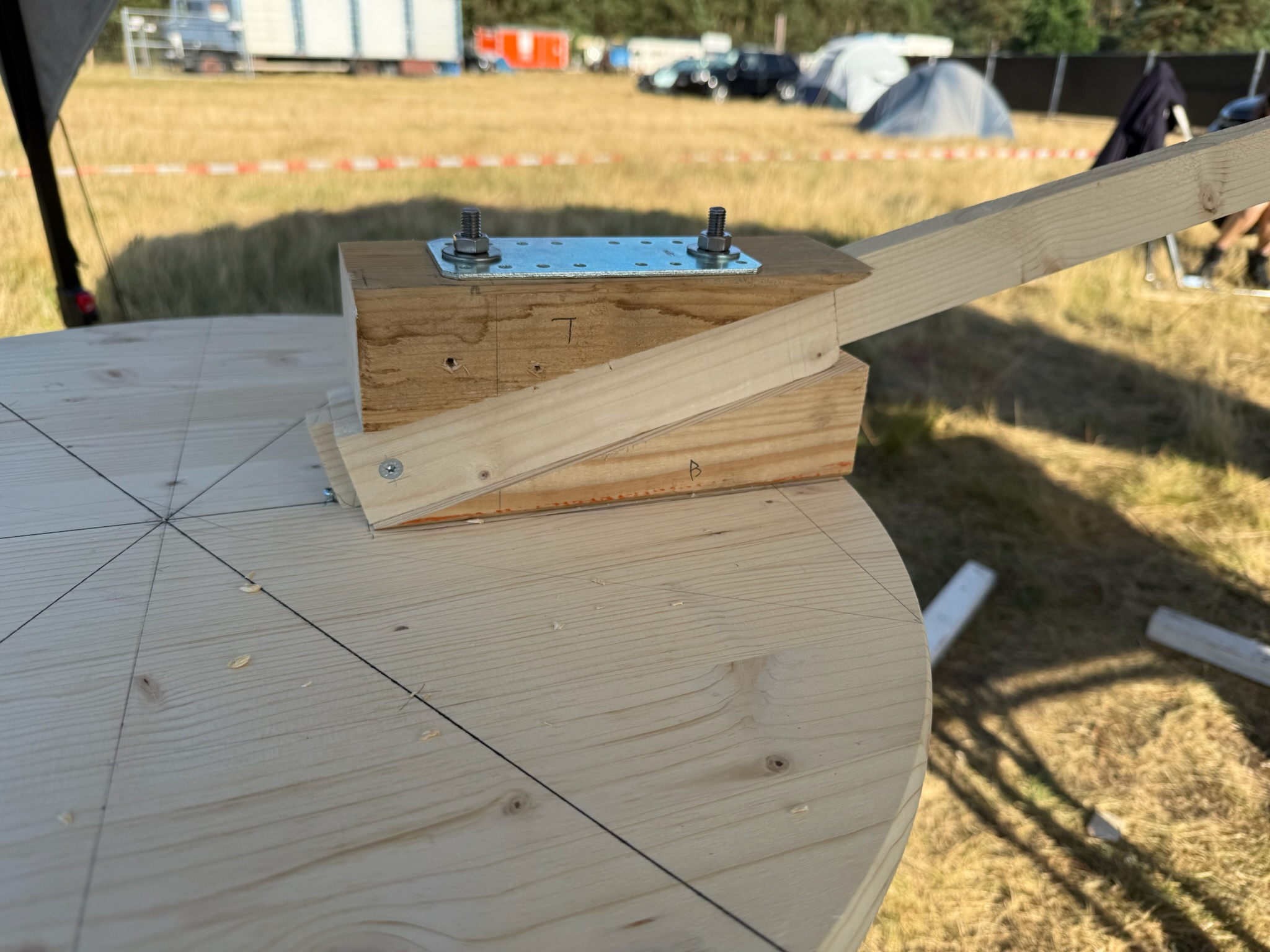
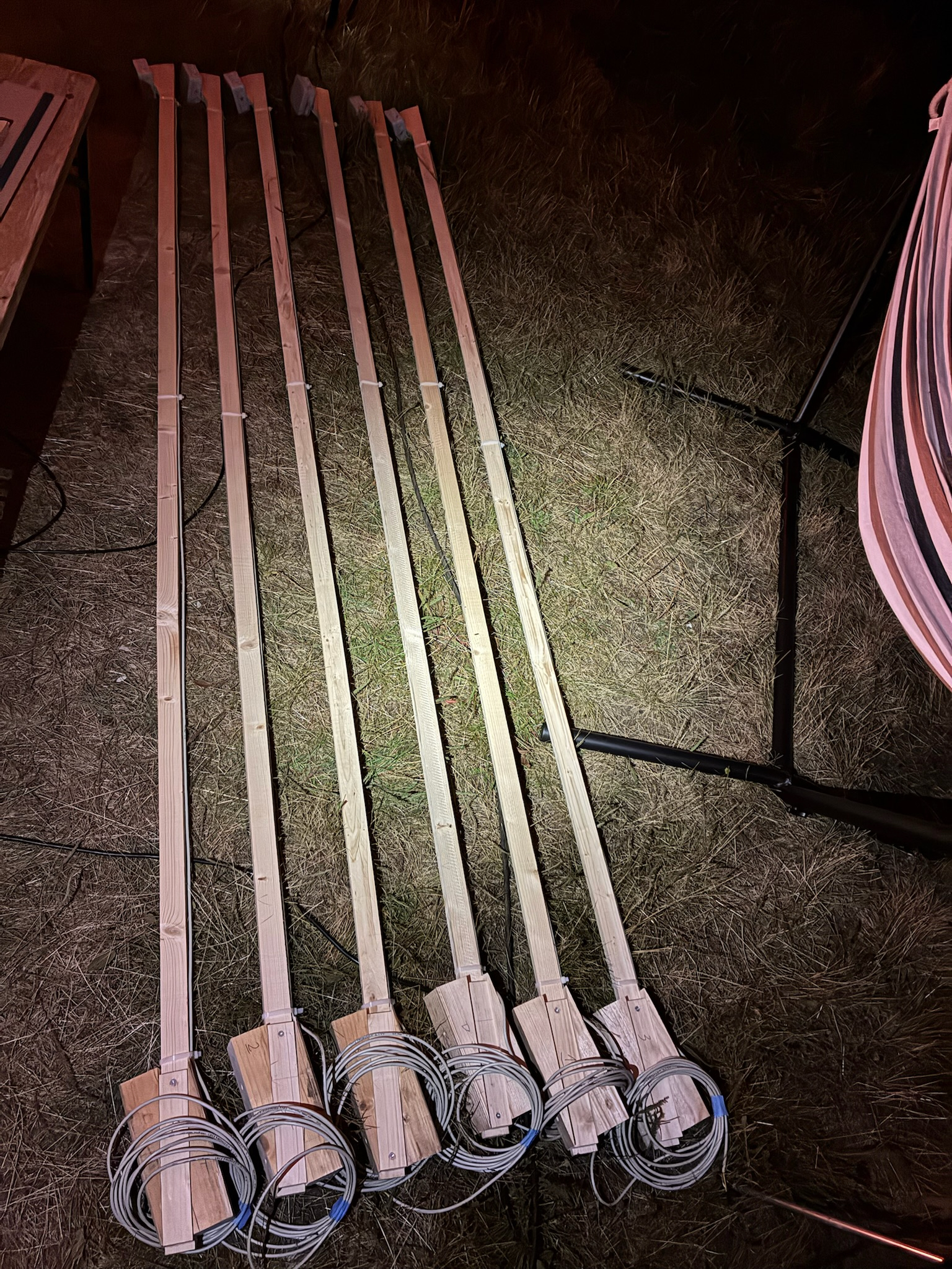
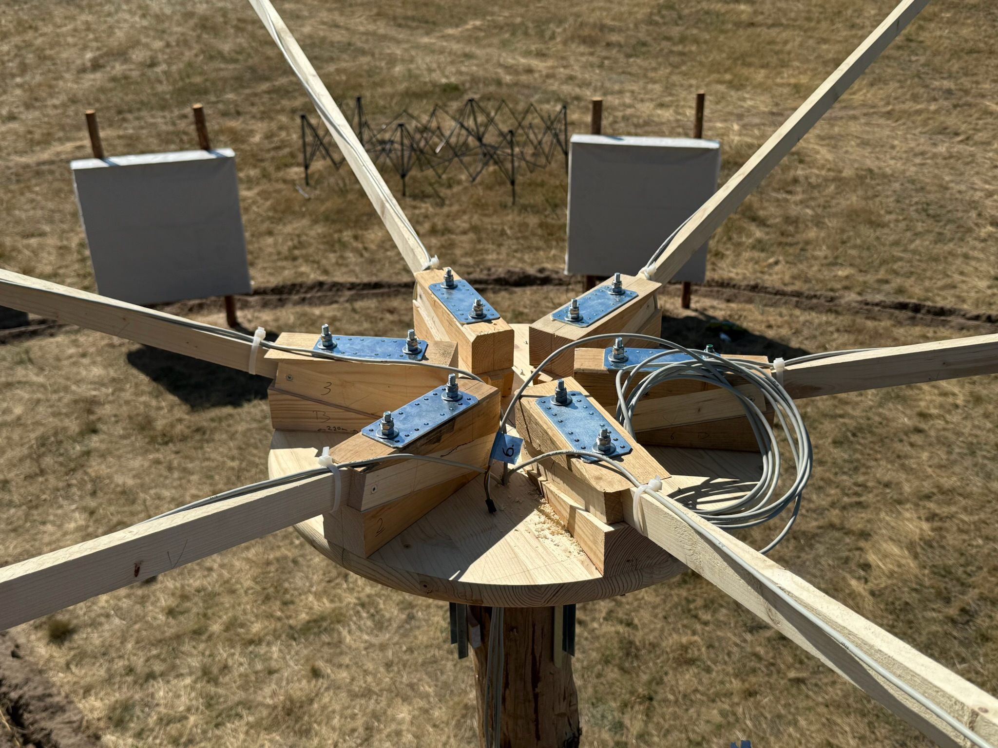
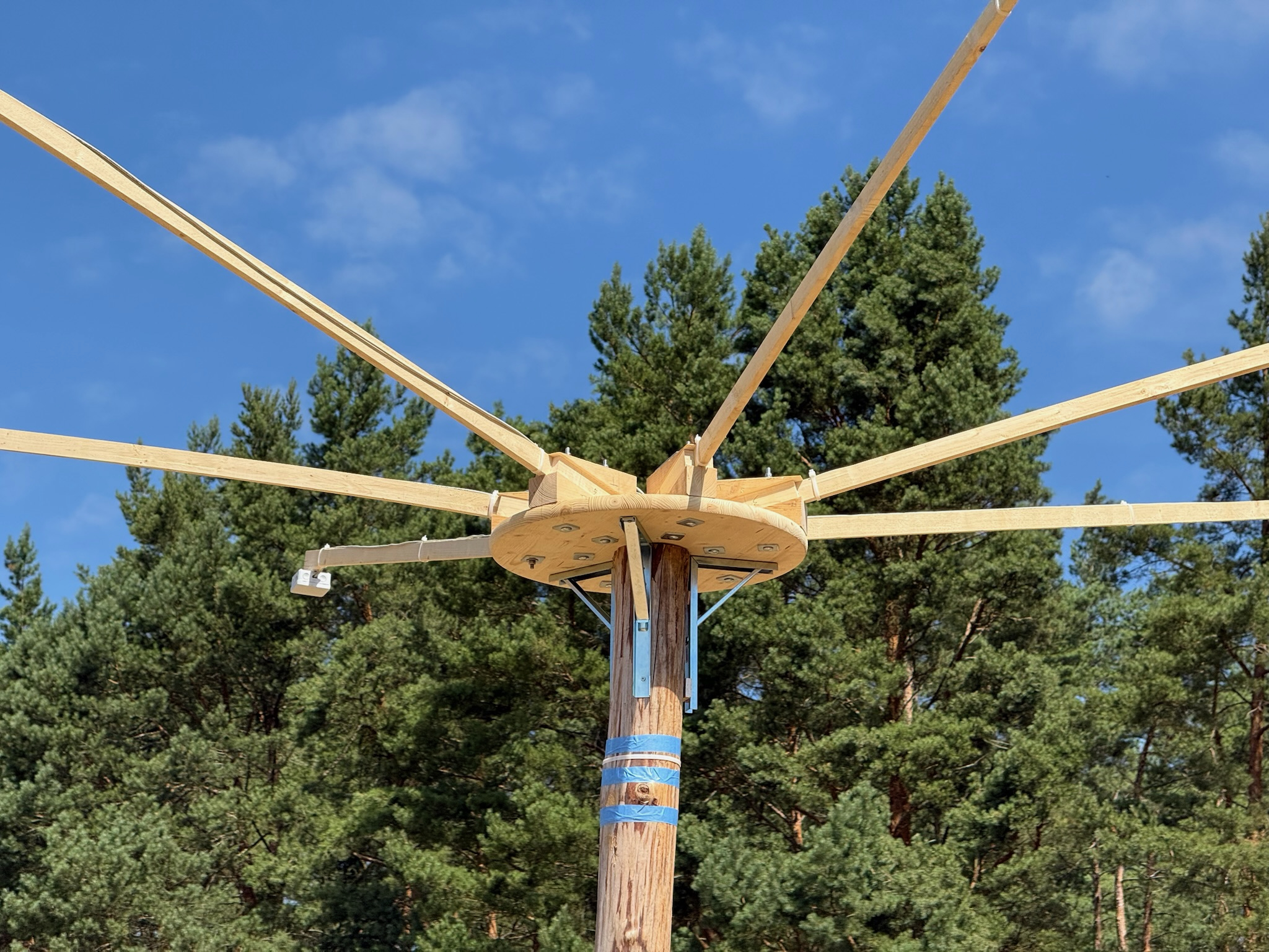
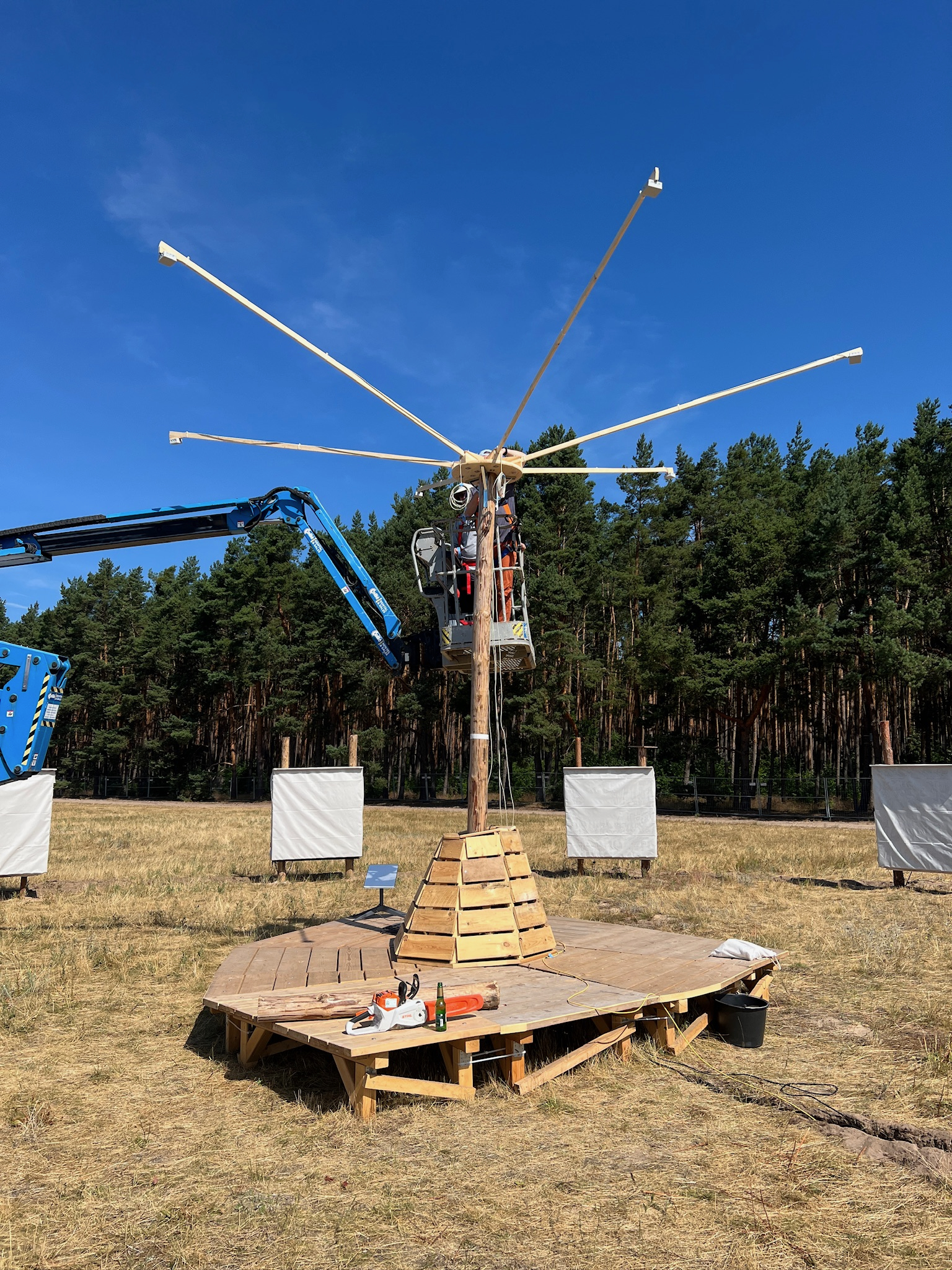
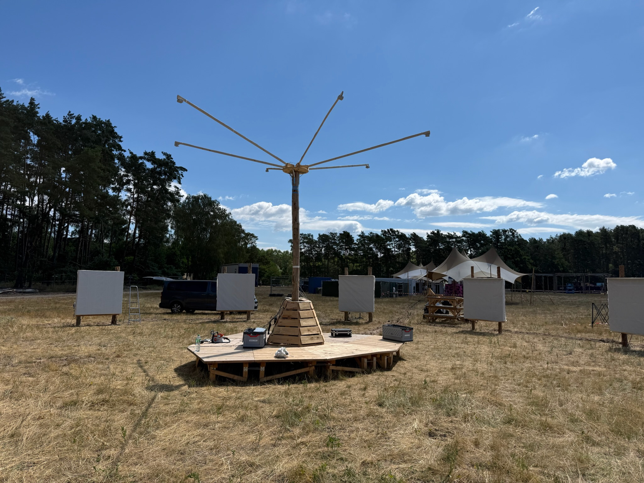
As you can see in the pictures, the mast was slightly crooked so we had to adjust one of the heavy duty braces to make it as straight as we could. We pre-assembled as much as we could the night before because our allotted time with the crane was limited. In the end the actual assembly went quite smooth. We first mounted the base plate with a center screw on top of the mast. Then we added the heavy duty braces which made the connection between mast and base plate very stable. Lastly we mounted the arms one by one and drilled a hole to get the cables down to the platform.
In the end, I was super happy that my initial idea worked in reality. I’m glad I decided to build it in CAD first, as this allowed me to experiment with the dimensions of the individual parts and obtain precise measurements for the actual build.
Last but not least, I’m very thankful for all the content on Jonas Winkler’s YouTube channel. I bought many of my new tools based on his videos, and almost every tool I brought to the site proved useful in one way or another. An additional thank-you goes to Michael Truppe and his YouTube channel, “Lets-Bastel” which provided further context, inspiration, and motivation.
I hope there will be a new challenge like this in the not too distant future! I had a blast!
Appendix A: The Gear List
As if this post wasn’t long enough already … but some of you will ask about the tools I have used so here is a list of everything I used for this project and the shelf project that worked well, that I would buy again, and that I can recommend. I have no affiliation with any of the mentioned brands and shops. (A notable alternative to Dictum or at least with a complimenting catalogue is https://www.feinewerkzeuge.de)
Measurements and Marking
- Shinwa® Tape Measure »Fit Gear«, 5,5 m
- Shinwa® Precision Rule, incl. Stopper, 150 mm
- Shinwa® Precision Rule, incl. Stopper, 300 mm
- Shinwa® Mitre Square
- Shinwa® 3-D Mitre Square, 45°/90°
- Zebra »DelGuard« Mechanical Pencil, 0,5 mm (best mechanical pencil i’ve used so far)
- Starrett® Automatic Centre Punch, 18A
- Gemred gemred 82305 digitaler winkelsucher 7-inch winkelmesser
- Mitutoyo 500–196–30 Absolute AOS Digimatic 150 mm
- Matsui Precision Try Square, 150 mm
Clamps
For clamps there are two major brands that you can basically get any clamp type from. I’ve started using Piher (Spain) clamps and I’ve been very happy with them. There is another reputable brand called Bessey (Germany) which I’d also recommend.
- Bessey® Spannelement TW-KLI für Multifunktionstische
- Piher Micro Quick
- Piher MINI QUICK T-TRACK
- Piher TPAL (T-Track clamp)
- Piher TPAL (Forged Steel T-Track clamp)
- Piher LIGHT PAL 30cm
- UJK Guide Dogs, Pair, Height 12 mm
- UJK Guide Dogs, Pair, Höhe 50 mm
Power Tools & Accessories
As you can see, I am a Makita enjoyer. Every Makita tool listed here, I’d buy again. Some people will say tools from $Otherbrand are so much better but I would say that in each tool category, Makita has good and very good options. It is usually the cheapest/lowest tier which are the ones that aren’t that good.
Stating the obvious: Once you’ve decided on a battery eco system it is more convenient to stay there. Plus Makita is one of 3 or 4 independent power tool companies which i sympathize with (see this info graphic). That being said – other people may choose different eco systems and thats ok too.

All links are to German stores and websites. But you should be able to find them on english websites with the provided model names.
- Makita DDF484RTJ Drill
- Makita DTD173Z Impact Drill
- Makita DSP600ZJ Plunge Saw
- Makita DRT50ZJX2 Router
- Makita DAS180Z Blower
- Makita Guide Rail 1m 199140-0 (I have 2 of those with connector)
- Bosch PRO FRÄSER-SET GEMISCHT, 30-TLG.
- VESSEL Bitsatz Impact Ball 31 Teilig
- Star-M Multibohrer einzeln – 6,35 mm Bitschaft (¼″) 20mm
- Wera Kraftform Kompakt 60 RA-R 1
- Bosch PRO WOOD HSS HOLZSPIRALBOHRER-SET 7 TLG.
- Bosch PRO WOOD HOLZSCHLANGENBOHRER 8mm x 235mm
Hand Tools
- Japan Saw TEMPLE TOOL Ryoba – 240 mm
- Stanley FatMax Metal Saw
- Stanley FatMax Pro 25 Cutter (seriously one of _the_ best cutter knifes)
- Wiha Soft-faced hammer “Safety” medium soft/hard
- KNIPEX Cobra® 125
Portable Work Bench
This one deserves its own section. All the tools are almost useless if you don’t have a proper work surface and since I don’t own a house with a proper workshop and I want to be able to do projects where mobility is a decisive factor, I was looking for a mobile work bench. At first I was considering something like the Metabo MWB 100 but it seemed too heavy and bulky for stowing it away in my apartment. Then I stumbled across the Bora Centipede and eventually bought it.
This is one of the best purchases ever. It is so easy to move around, stow away and to set up. It is so incredibly solid once assembled. I can’t say enough good things about this thing. Of all the things this would be maybe my top recommendation if you’re looking for a portable yet stable temporary work surface.
Appendix B: How to find the exact center of a circle
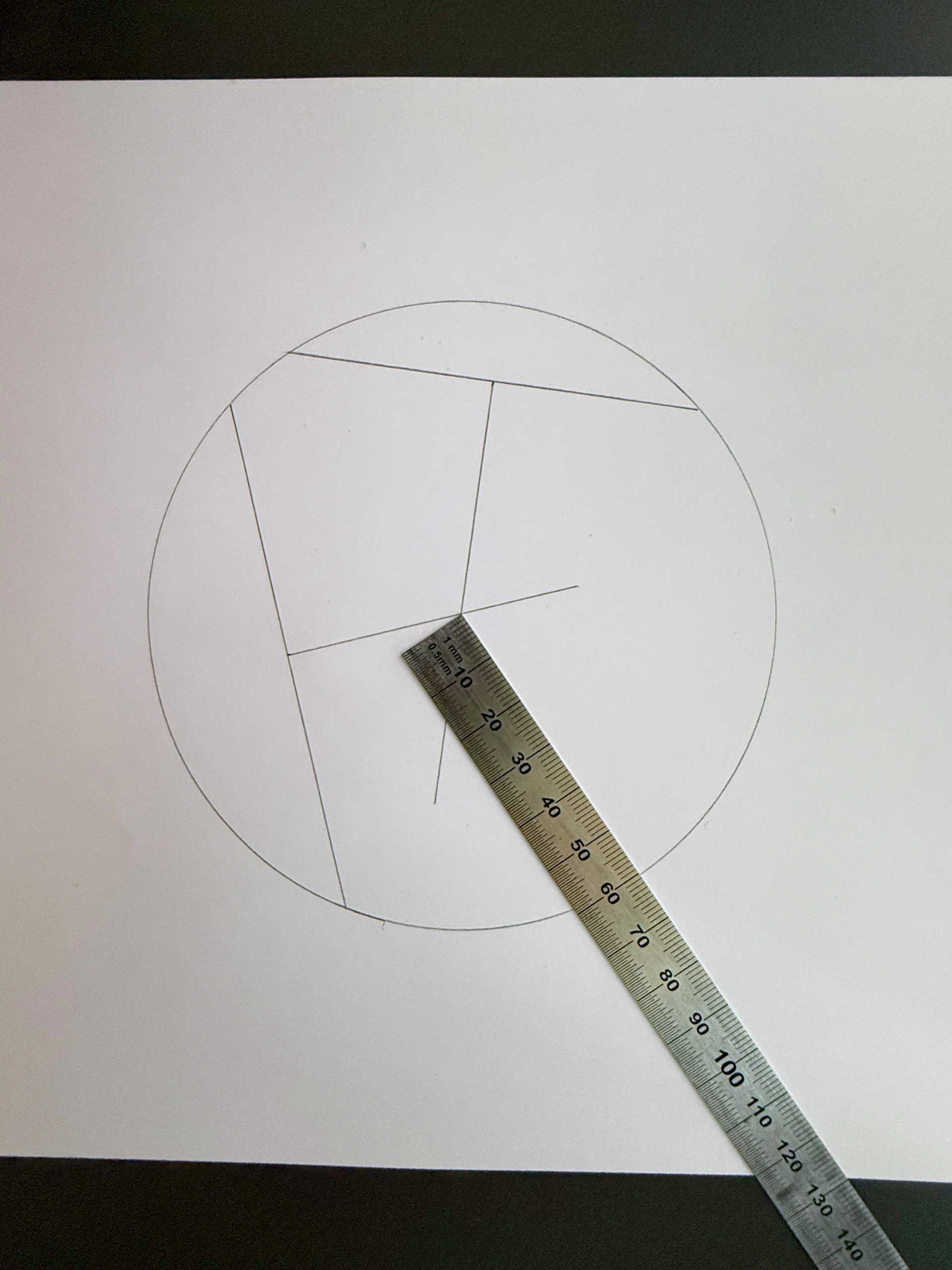
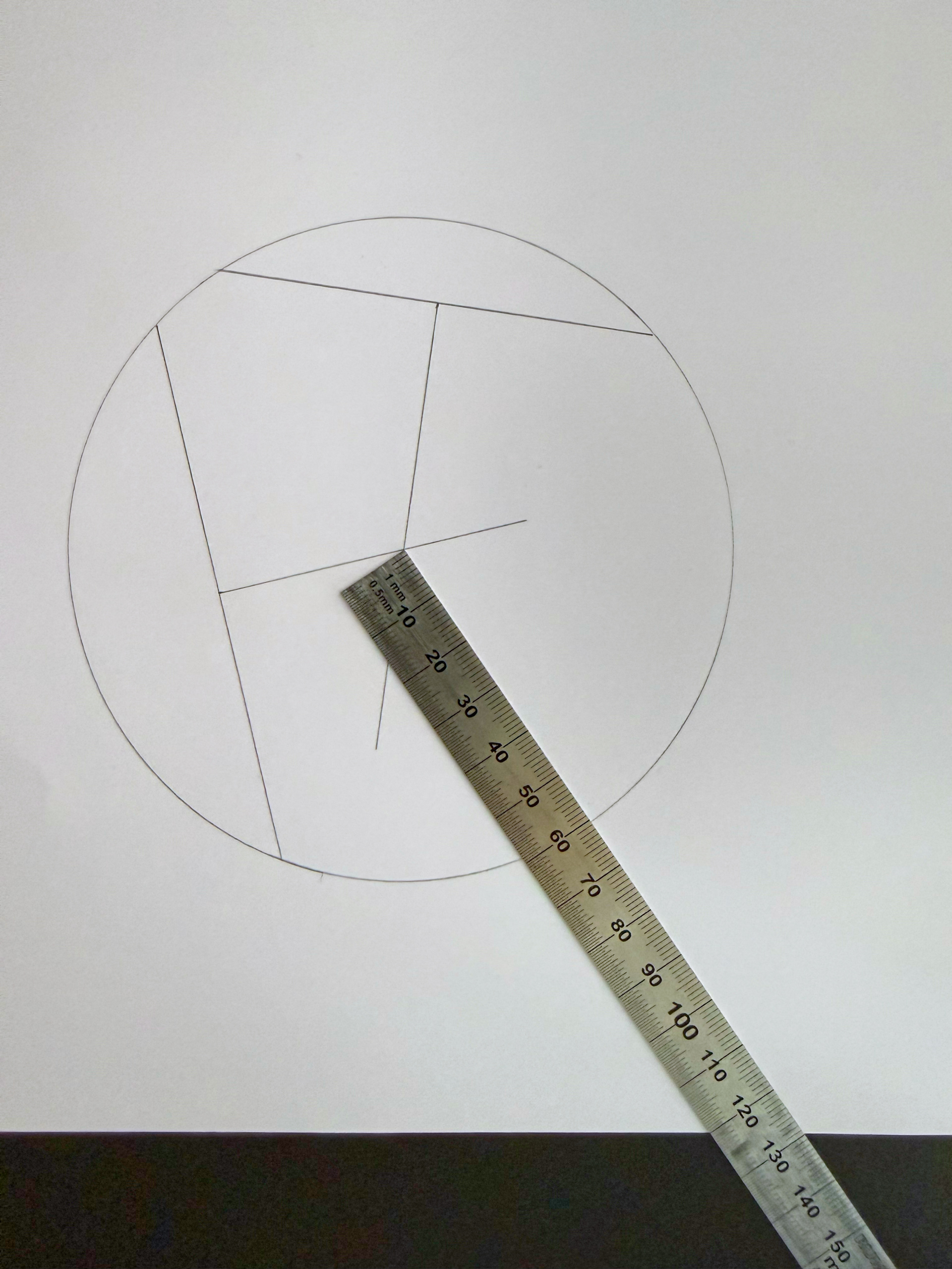
For this project it was necessary to have equal spacing between all 6 arms. The math is quite simple: 360º / 6 = 60º and there is a neat little trick to divide a circle into 6 equal parts by tracing the radius along the edge and then connecting all intersections with the circle like so:
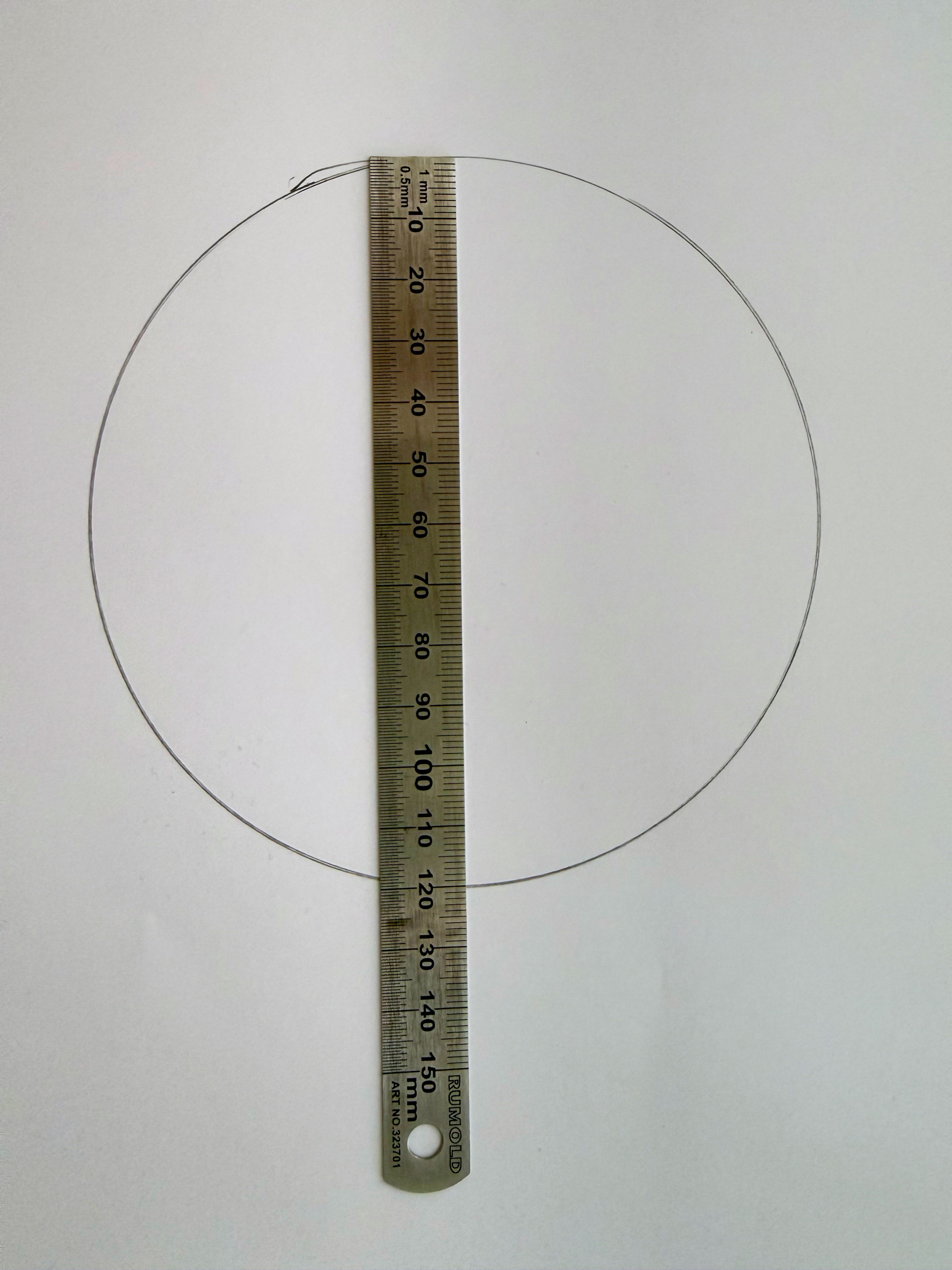
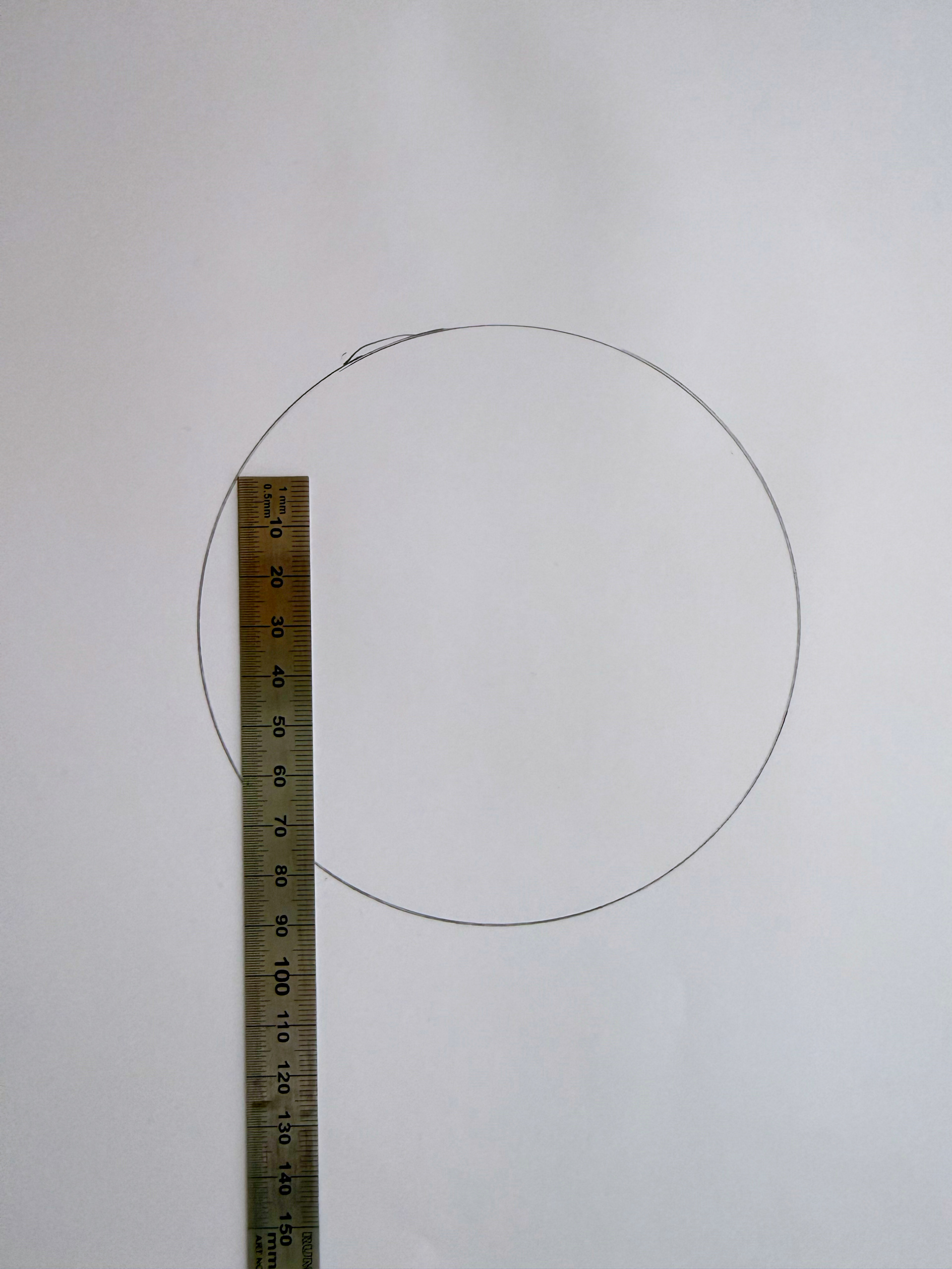
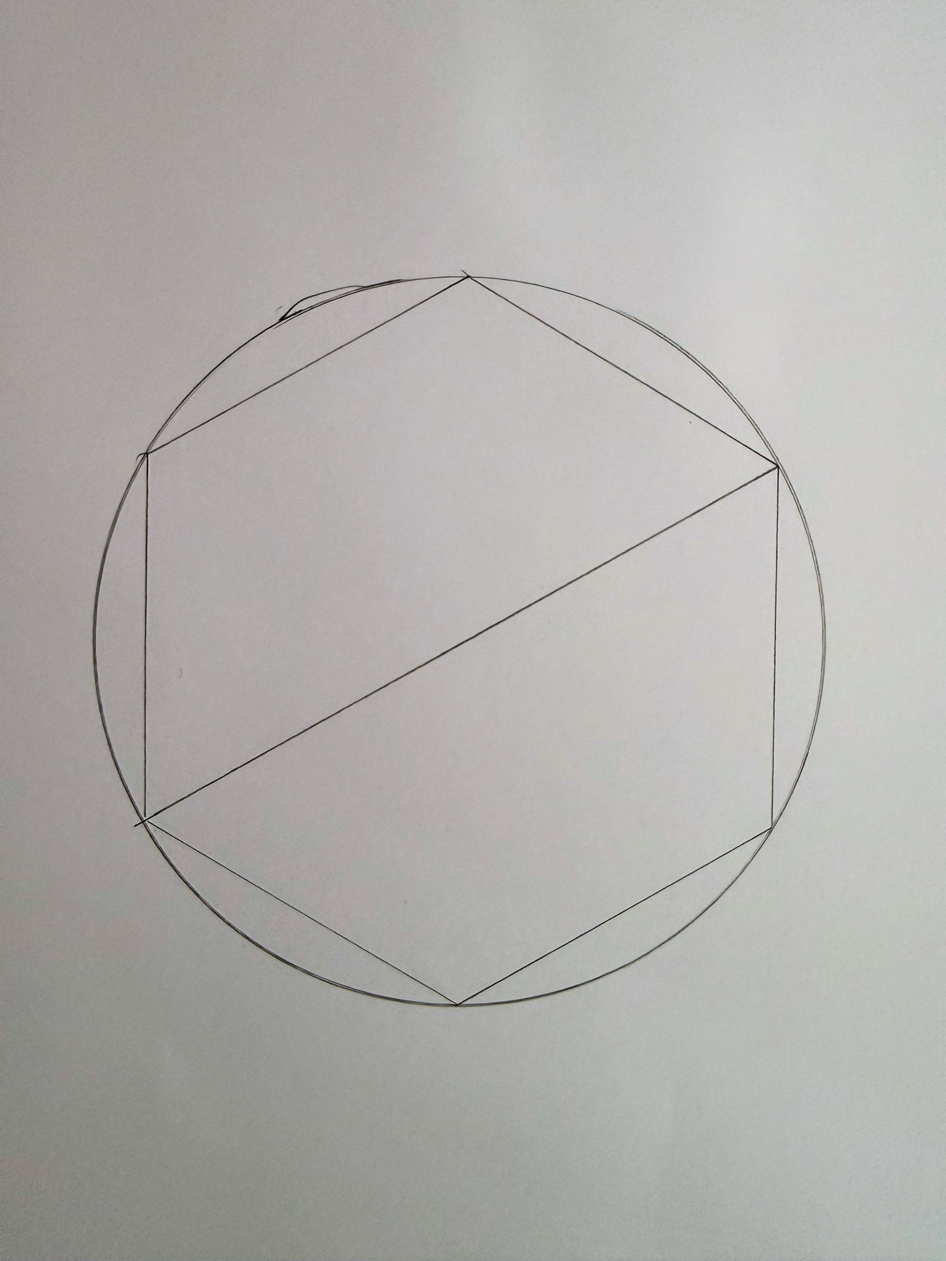
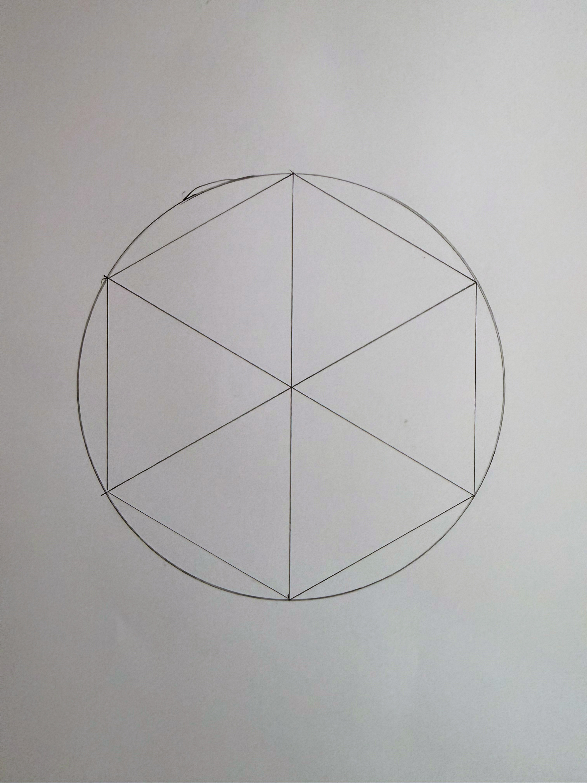
At small scales this works remarkably well and the slight imperfections don’t really add up to much. The center looks like a perfect center point. However using this technique on a 60cm diameter disk with rounded edges led to somewhat catastrophic results when attempting to determine the true center of the disc. Basically I ended up with a rather large triangle instead of a center point. With this technique, measuring errors compound quickly.
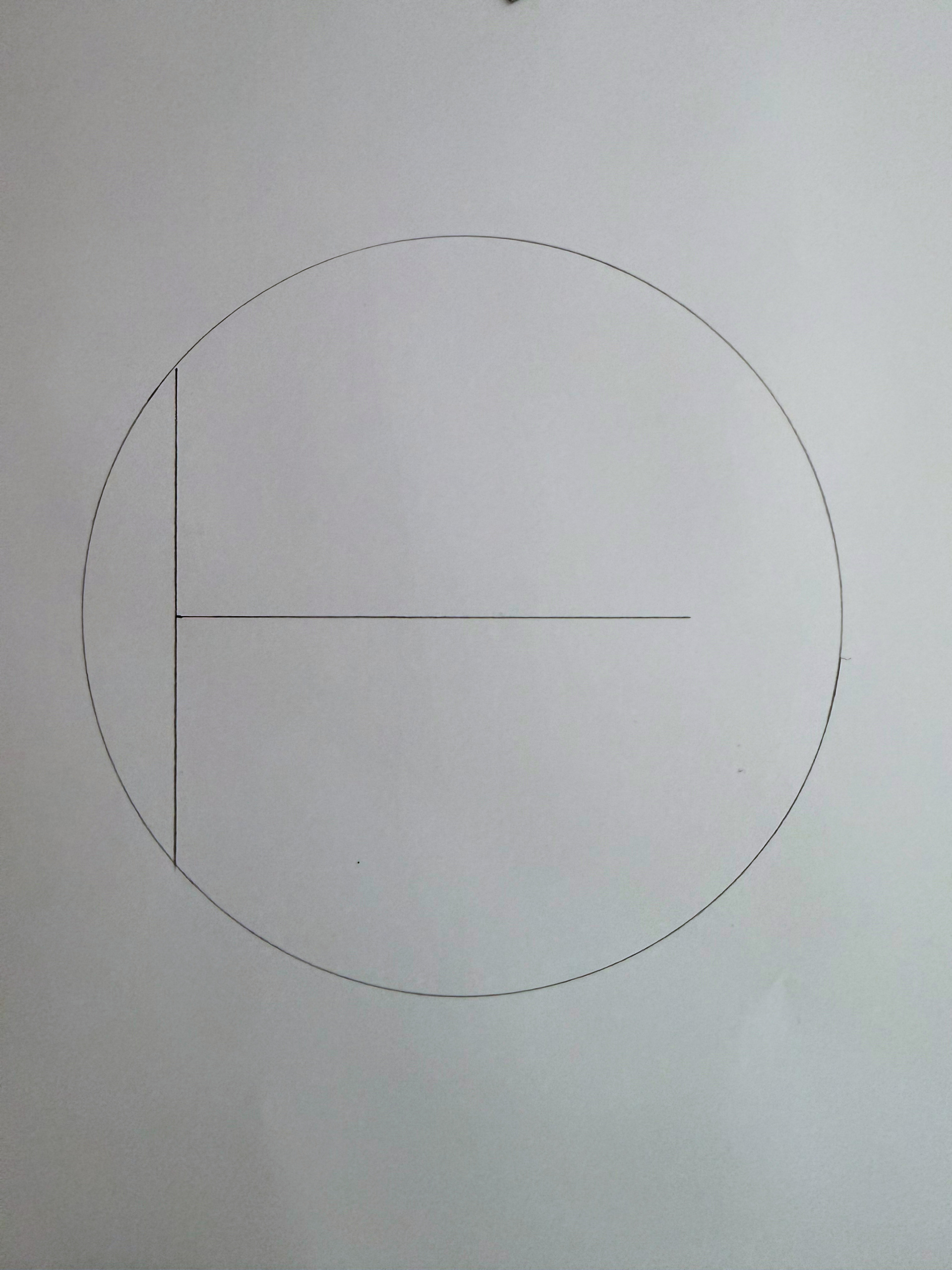
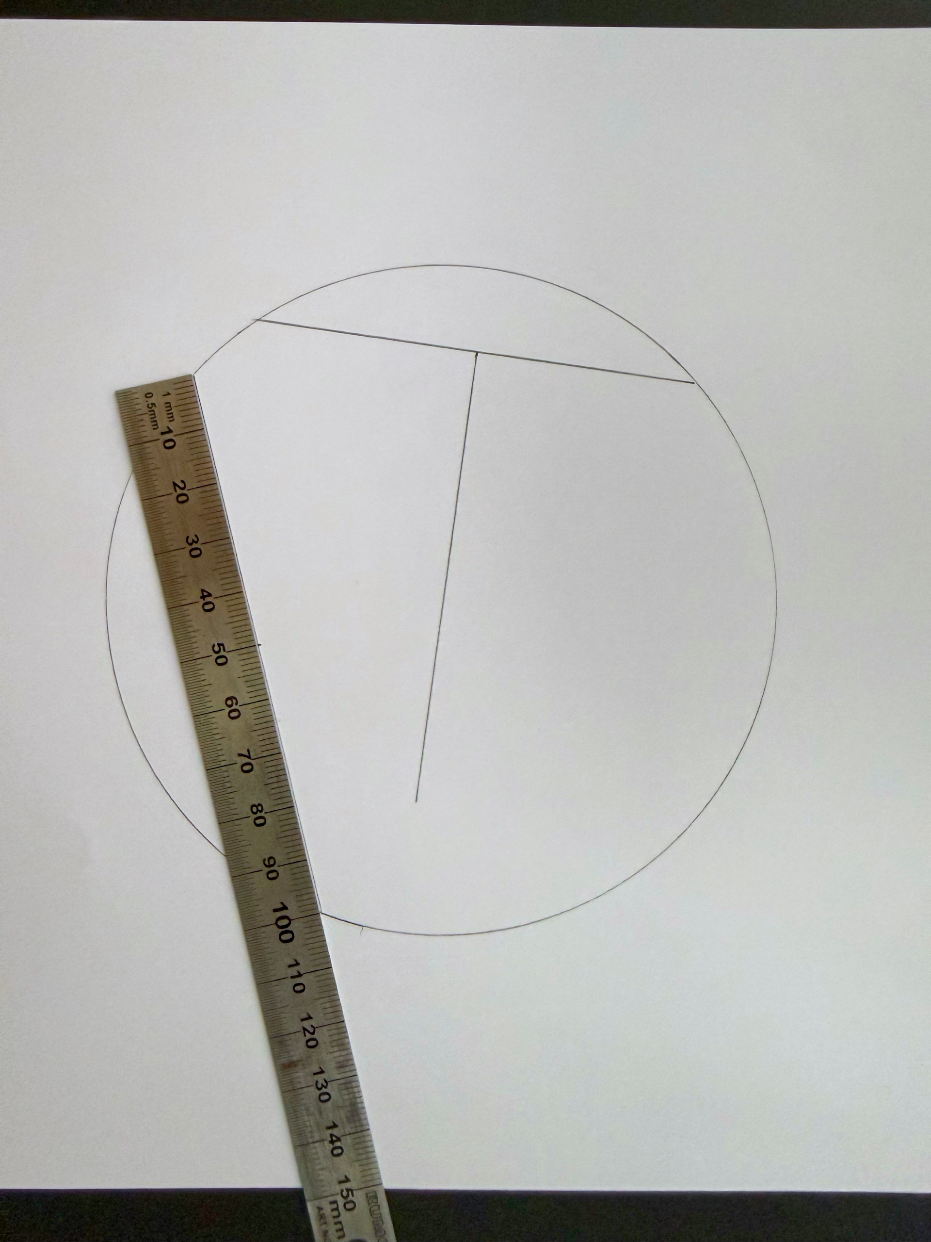
The method that I’ve used to precisely find the middle is as follows:
- Draw any line from edge to edge in the circle
- Determine the middle of that new line
- Draw a line from that middle point at a 90º angle
- Do all of the above at least one more time
- The center is where those 90º center lines meet
Thanks for describing your process and congratulations on shipping something real.
I would like to recommend kurswerkstatt-saar.com for online courses and blog in German. Also, feinewerkzeuge.de sells high quality woodworking tools. I have no affiliation with both; I am just a happy customer.
Regards
Steffen
Ah! I wanted to mention https://www.feinewerkzeuge.de in the post as well – thanks for the reminder 🙂
Please watch the really old Jonas Winkler youtubes, they are much better than his actual clickbaity shit and i learned a lot of them.
I like and recommend the channels of Heiko Rech and Dominik Ricker.
Dominik was the host of Maschinen-Handel-Meyers Youtube Channel a long time ago, and these are still good ones, his own channel is also very good.
I am Fusion360 user (as i started with 3d printing stuff), but i consider to give Onshape a try now. Not sure if i like the online and public setup…
I had a lot of fun to read this article, and i noticed that you avoided that often made cheap tools are good enough error. All tools you bought look descent to get the presision you want (and need to be satisfied).
I started in a similar way (a router, a miter saw, a 22mm multiplex sheet (sawed to size by the hardwarestore which i plunge-routed into a Multifunktionstisch) on my balkony to build my first workbench.
I learned very quick that i must have a workshop and rented a 20′ shipping container for over a year to build my workshop in. Fun times, i learned really a lot (and bought over the time a lot of tools).
Wood is still my most loved material to build things and be creative.
Be aware of a common problem: I got a very heavy form of G.A.S. (gear aquisition syndrome) and hardware creep. Avoid that at all costs. 🙂
I have thoroughly explored his channel 🙂
Great write-up — moving from pencil-and-paper to a CAD model is exactly where the precision starts showing up, and I like that you treated the sheet-cutting step as part of the loop rather than an afterthought. Feeding the part list into a cut optimizer before ordering the plywood is what turns a design into a one-sheet build instead of a pile of offcuts — the same trial-and-error you hit with the Sortimo shelf. For anyone at that stage, CutListEngine is a free browser-based sheet-cutting optimizer: you drop in your parts and sheet size, and it works out the most efficient layout before you buy the wood. It pairs well with Onshape’s cut lists. Nice work on the Polychrome arms, too — 15° over a 3 m span with simple tools is genuinely ambitious.
Your point about poor measuring and marking causing imperfect fits is spot on — I’ve found that spending time on a precise plan up front saves all the forcing and fiddling later. That same principle applies to arranging a room: using a feng shui bedroom layout tool before moving furniture can prevent a lot of awkward, cramped placements.
feng shui bedroom