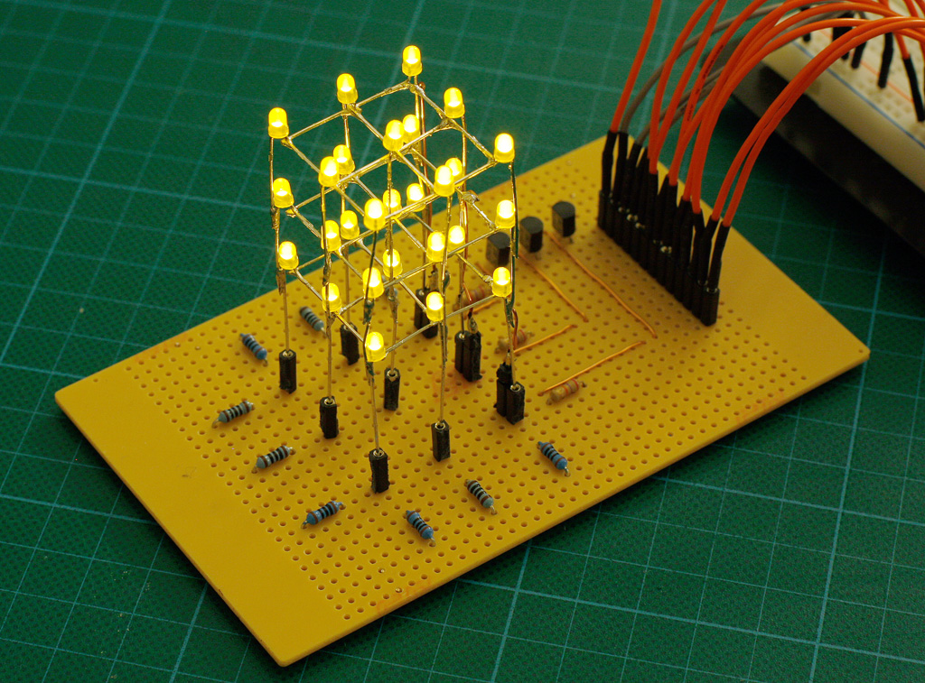
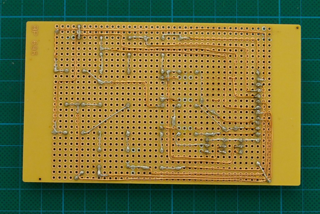
Until now I haven’t posted any schematics. This is because the cubes I’ve shown so far were too trivial. This also the case with this 3x3x3 LED cube and its board. As you can see it uses a lot of wires. 9 Wires for addressing the LEDs on a layer, 3 more wires for multiplexing / switching the layers and one more wire for GND. The Arduino Board provides enough pins and so no fancy techniques are necessary yet. While the board looks clean and simple on the top, the actual wiring on the bottom is a little more complicated.
Even a 3x3x3 cube involves some work. The only new concept here is the use of transistors for switching the layers.
Power
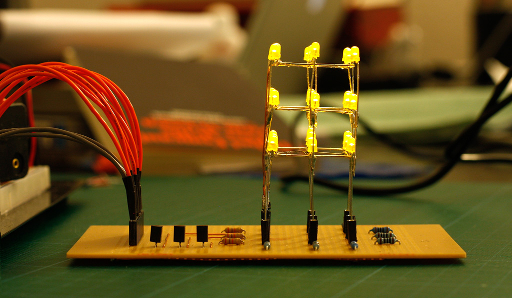
This cube has common cathode layers and common anode columns. This is because each column is directly connected to one of the Arduino IO pins. These pins can provide a current up to 40mA. A typical LED needs around 20mA for full brightness and since there is only one layer connected to GND (-) at the same time each column only draws 20mA at any given time.
The layers are connected to transistors which allows switching the layers to GND with three IO pins. The transistors are all connected to a common GND which has the advantage of requiring only one GND wire instead of having individual wires to for each transistor.
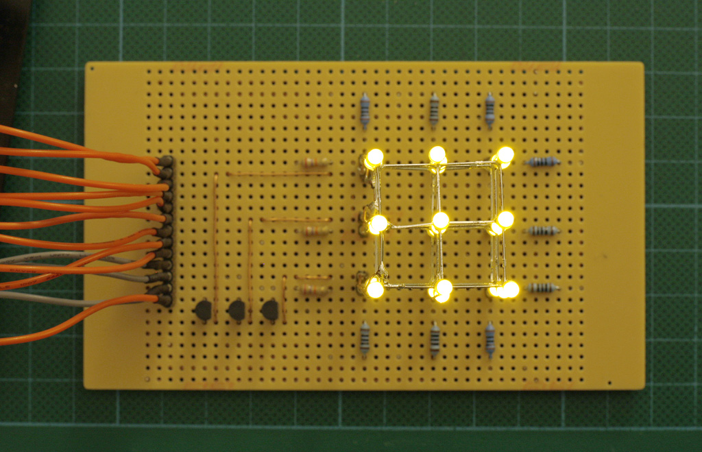
Also notice that all the LEDs are connected via the cathode which means that if an entire layer is lid up at once, a 180mA (9 * 20mA) are flowing through the transistor.
I don’t have the code for running the cube on that board anymore but I build a second board with shift registers which I will show in the next post.
I’m trying to make one of these and i was wondering why do we need the transistors for the 3x3x3 but not the 2x2x2??
The 3x3x3 uses more power per layer than the 2x2x2 which cannot be powered by the Arduino output pins.
Thanks, after i posted i did reveal that the arduino can only sink up to 40mA.
can i ask what transistors you used and what is the value of the base resistor?
Does this sound right: if i want 180mA for the 9 leds then the base should be 1/10 (rule of thumb for transistors as switch, i guess.. )of that so the base current should be about 18mA.
Following an equation that Ic=B*Ib
BTW thanks for posting these cool projects ^_^
Well to be honest – when I built the 3x3x3 cube I used BC 547 which were included in some starter kit I bought. Since I used the 3mm LEDs they were good enough. For my other Cubes I used Mosfets which allow much higher currents, switch faster and can sometimes be driven directly by the Arduino.
For this small cube I would look for a transistor with a slightly higher collector current. This german electronics site has a nice transistor overview:
http://www.mikrocontroller.net/articles/Transistor-Übersicht
how to make a led cube diagram 3*3*3
Use Fritz, it’s the best free one out there and it has all the audrino parts in it.
I would like to know what you used to solder the board. I have never see a board so clean. Or seen the brass looking material used. I’ve searched everywhere and can’t seem to find what you used. Thanks
The wire is coated copper wire. You have to heat the parts you want to solder before so the coating is removed. In german its called “Kupferlackdraht”. The board itself is a prototyping board as in https://www.radioshack.com/products/multipurpose-pc-board?variant=5717554117