Next Stop: 27 LED Cube Street

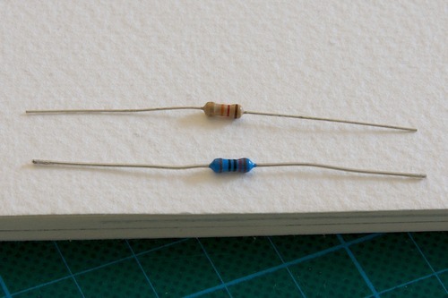
Building the 2x2x2 cube was really easy. We literally bought the Arduino, a couple of LEDs and cables (as described here), put it together and it worked. Of course we wanted to go to the next level immediately, just like in a video game. With the same principles we built a 3x3x3 cube but this time it featured resistors in series with the LEDs, transistors for switching the levels and a socket which allowed us to switch the board or the cube easily. I will explain each step starting with the soldering.

Soldering the LEDs together

Basically there a different ways to do it but all variants share the same principle of having layers and columns. Also its best to have some kind of grid to make sure the connections are as straight as possible.

One way of building a cube is to solder horizontal layers and stack them on top of each other by connecting the cathodes, only using the LED pins. 

Instructions for horizontal layer soldering:

1. Get cheap wood like MDF and draw the desired grid onto it. For regular LEDs the grid width should be 2,5cm.

2. Drill holes where the lines of the grid cross and make the holes 5mm wide (if you’re using regular 5mm LEDs). Start with a 4mm wood drill which could be sufficient.

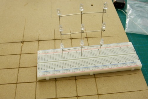
3. Bend the anode (longer LEG) 90° like you can see on the picture below and put the LEDs inside of the holes

4. Solder the anodes together

5. Cut of two anodes (longer leg) of other LEDs and use them to stabilize the layer

6. Cut of the overlapping wire and the first layer is complete

7. Bend the cathodes to the side like you can see it in the picture so that you can stack the layers on top of each other. You can skip bending the cathodes for the last layer. In the following picture I did only bend the front LEDs. 

8. Build two more layers and solder them together.

Instructions for vertical layer soldering:

The other way of soldering together a cube is to build vertical layers. This has the advantage of being able to switch single vertical layers. In the horizontal version it is close to impossible to fix a broken LED in the middle of the cube. Also allows to build larger cubes that a more solid and straight. This is how you do it:

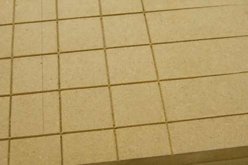
1. Get some cheap wood like MDF and draw your desired grid onto it. Then use a saw, a screwdriver or a cutter knife to cut out the grid like in the following picture.

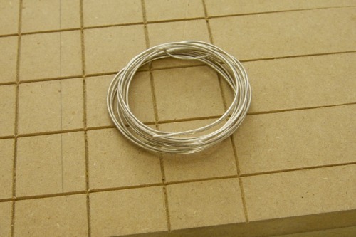
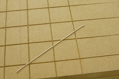
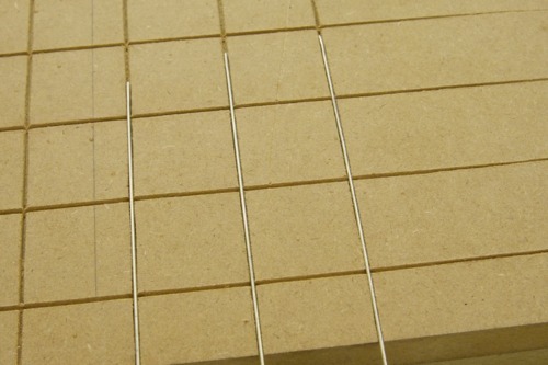
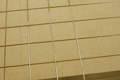
2. Get some copper wire and cut it to pieces. Then use two pliers to straighten the wire. Grab the ends of the piece of wire and pull it straight. You can feel when the wire is extending. Release it carefully and you should have a straight piece of wire. I used copper wire which is mixed with silver. I couldn’t find any good translation for “Versilberter Kupferdraht”.

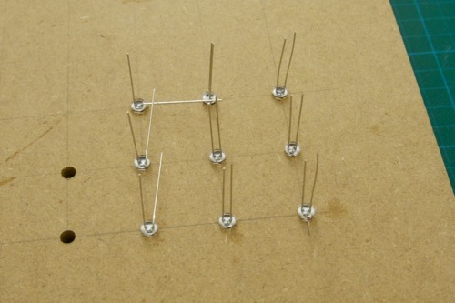
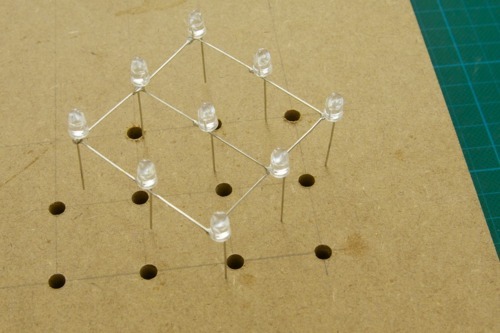
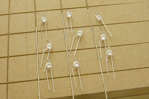
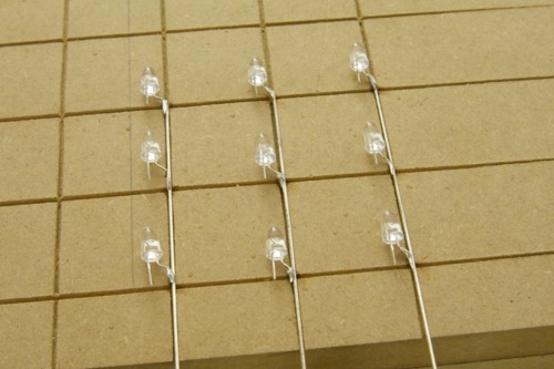
3. Get 9 LEDs and bend them like you can see on the picture. Then shorten the cathode

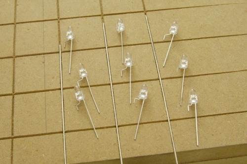
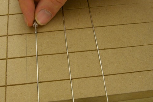
4. Hold the soldering iron onto the junctions and apply solder. Then grab an LED, head up the solder on the wire, hold the LED like on the picture. Distribute the solder and remove the soldering iron while still holding the LED for a second or two.

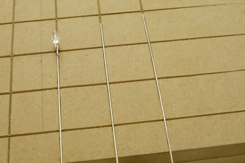
5. Attach all the LEDs that way. You can shorten the anode as well by the way.

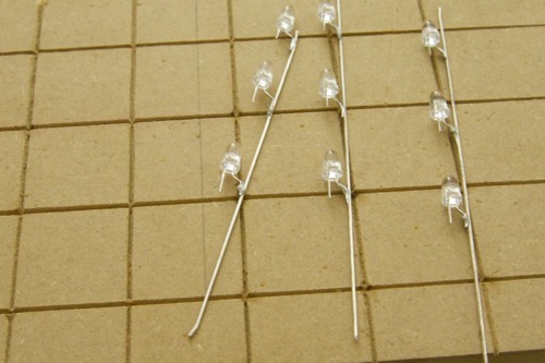
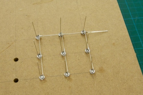
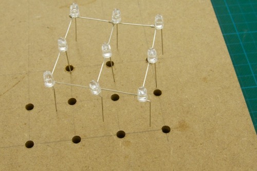
6. Lay out the columns onto the grid. Cut and straighten three more wires and connect the LEDs horizontally.

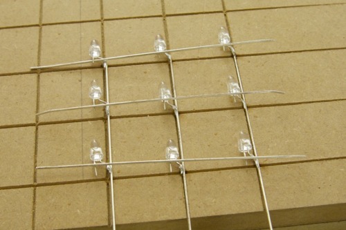
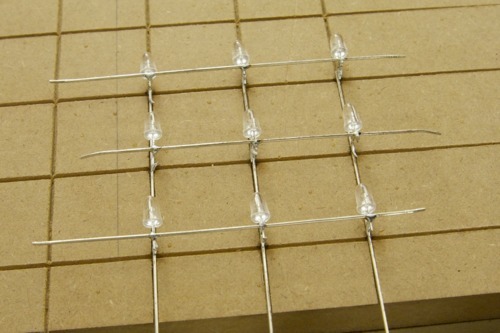
7. Cut of the overlapping wires and you have your first vertical layer

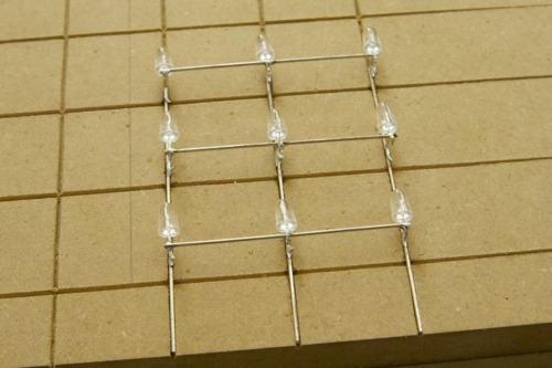
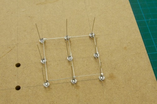
8. Now build two more layers. Put them next to each other, then connect these LED walls horizontally with some more wire but just on the outer sides. Does that make sense? This cube, even if its built from vertical layers will have horizontal common anode layers just like the other cube had. Its just built in a more modular way. Therefor the vertical LED modules need to be connected horizontally in each row. 

Now while this seems more work in the beginning, it saves a lot of hassle later on. Imagine building a cube in the horizontal layer way. When the LED layers are stacked on top of each other, 9 cathode connections need to be made every time. As you cube grows it is getting harder and harder to solder it straight. A mentioned before it is also getting harder to extract an LED from the middle. Imagine building a 10x10x10 cube where 100 cathodes need be be soldered together for each layer! 

With the vertical LED module approach the stacking is already done. They can be be easily plugged one after another into their sockets and only need a few connections horizontally so connect them and to stabilize the cube. Since the horizontal connections are mostly on the outside of the cube, they can be easily removed to take out / replace individual modules.

Finally the cube will be more stable if straightened wires are used instead of the LED pins. I build a 5x5x5 test module which I could stick into my breadboard. I even attached a bunch of cables and its still stable.


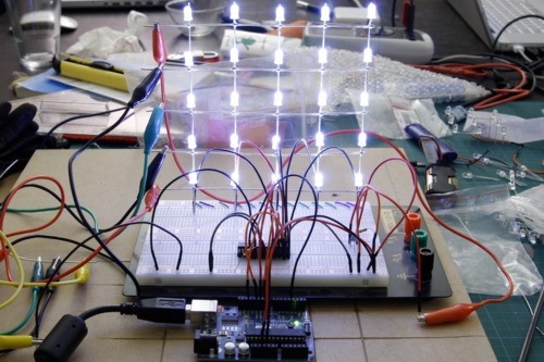
This 5×5 matrix is again completely powered by the Arduino which is connected to my MacBook Pro. There are only a few Arduino pins used. Two of them supply the power and five control the LED driver chip which is called TLC5940.

If something about the soldering part is still unclear, contact me please.

2x2x2 Multiplexing Demo

Today I decided to use the small 2x2x2 cube to demonstrate multiplexing and so I got out my breadboard and connected it in most simple way possible. All six cube pins go directly into the Arduino IO pins. I uploaded the program which I mentioned in one of the previous posts and it worked right away. It is actually bad to connect the LEDs directly to the Arduino without any resistor in between but the Arduino is very forgiving and works with like that with smaller loads. This should not be a permanent design pattern however. The video shows that the LEDs can not be addressed individually when powering both layers because they share cathodes horizontally and their anodes vertically. Therefor its not possible to switch on the upper left and the lower right LED individually at the same time as all the other LEDs in the same column would light up as well. This is shown in the beginning of the video. To solve this problem the layers are switched on one after another in such a fast way that the human eye does not recognize it. This is the basic principle for most kinds of LED matrices. Again the corresponding program is trivial. Next up: Bigger cubes and more advanced techniques.

Vive la résistance!

A short word on resistors. There are two common kinds available. The brown (carbon film) and the blue (metal film) ones.

The metal film resistors are generally preferred for the following reasons:

  • They have a smaller tolerance (1%) compared to the carbon film resistors (5-6%). That means that the actual resistance is very close to what it says on the box. In contrast the carbon film resistors vary a lot more. A 100 Ohm carbon film resistor can have an actual resistance of only 88 Ohm which is quite a difference.
  • They can handle more load than carbon film resistors while getting not as hot. (0.6W compared to 0.25W)
  • They produce less noise. This is not that important but still its a benefit

I mention this because initially I bought two boxes of the brown ones and I didn’t know about the difference. The advantages are not big enough to throw away all my carbon film resistors as they still work but I prefer metal film resistors from now on.

But what parts are needed to get started?

After writing an introduction and posting the first cube its probably time to talk a bit about the necessary hardware. After months of fiddling around I take certain things for granted that were really difficult to figure out in the beginning. Therefor I will also talk about the necessary tools and materials starting with the basics in this post.

The most important things are:

  • Getting Started in Electronics by Forrest M. Mims III: This is such a great beginners book for electronics that I wholeheartedly recommend it to everyone. The cover doesn’t look too fancy but the content is just great. Trust me. You want that book to learn about all the basic electronics stuff.
  • Microcontroller / Arduino UNO: Quote from the Arduino website: Arduino is an open-source electronics prototyping platform based on flexible, easy-to-use hardware and software. It’s intended for artists, designers, hobbyists, and anyone interested in creating interactive objects or environments.” 

    Its ideal for beginners as it abstracting away many difficulties when dealing with microcontrollers. The Arduino board itself is error forgiving (as in short circuits) and offers everything that is needed for a quick start but even for more serious projects. It can be easily connected via USB and has a very good documentation. The website offers many useful tutorials and the community around it is very encouraging.

  • Soldering Iron: Obvious but necessary nonetheless. I bought a pretty cheap one from Weller called WHS 40 which has 40 Watts of power and although is not expensive it works really well. The only accessory I needed was a finer tip which is also highly recommended. Irons that have less then 40 Watts take too long to heat up and can get quite annoying to use. My next station will have a little more but for now it works great.
  • Breadboard: This allows easy and fast circuit testing. The first thing I do when I try out a new LED, Transistor or any other part is to get out one of my Breadboards and play with it. Its also helpful for debugging in terms of rebuilding a circuit.

    I recommend having two. One big one with lots of space and than maybe a smaller one which is more handy and more practical to carry around

  • (Flexible) Jumper Wires: Places that sell Breadboards are very likely to sell jumper wires as well. I have them in different lengths and colors and as breadboards, they are highly recommended. There are stiff and flexible ones and I prefer the flexible ones because, as the name implies, they’re flexible!
  • Multimeter: This is the most important tool for debugging and testing circuits. It does not need to be an expensive one but it should be digital and offer a convenient interface. I bought an Voltcraft VC270 and I’m happy with it.
  • Resistors: This might be obvious again but still its good to have a broad range of resistors at hand. I bought two resistor boxes which contain resistors from 10 up to 27.000 Ohm. They are constantly needed especially when following the autodidactic approach of learning. Its great to always be able to reduce or increase the resistance when needed.
  • Transistors: I’d say that similar to resistors its essential to have a some transistors at hand. There are some standard transistors like the BC557, BC547, BC337, BC327. These are very common parts for all kinds of circuits. Basically they are very fast switches that allow to switch higher currents and voltages than your micro controller can supply. 
  • Wires: Simple copper wire or enameled wire for connecting parts on boards
  • Perfboards or Stripboards: When its time to make a circuit more permanent then on a breadboard with jumper wires these are useful for easily soldering everything together using the wires mentioned above.
  • LEDs: I almost forgot.
  • Other Parts: Like switches, potentiometers, light sensors etc etc. They’re not necessarily related to the construction of cubes but its fun to play around with those parts anyway.

Alright. I will write more about hardware as needed.

2x2x2

In the first post I said that building small LED cubes is reasonable easy. Without much prior experience we (my girlfriend and myself) built this small 2x2x2 cube. Its really tiny and the soldering is sloppy but it worked. Unfortunately I can’t find the board that belonged to the cube so I there is only a picture of the cube itself.

Although this doesn’t look spectacular it shows a common principle for LED cubes. The one thing to notice is the number of wires visible. In this picture there are 6 pins / connections visible. If each of the 8 LEDs would be connected individually there would be 16 connections necessary to power the cube. Instead the LEDs are connected vertically by their anode (+) and horizontally by their cathode (-), forming two layers with 4 LEDs each. Now to power up a single LED the corresponding layer and the corresponding column need to be connected. If both layers are connected and one column than both LEDs of that column would light up. The principle behind all this is called multiplexing. This means that only one layer of LEDs is active at a given moment. So for a given picture each layer is activated after another in such a fast way that thanks to persistence of vision, the human eye does see the complete picture, without noticing that is composed of multiple steps. Does that make any sense? I should probably add a video or animated gif.

For smaller cubes its also not important whether the LED layers are connected via the cathode or anode. For bigger cubes its important but I’ll get to that later. Multiplexing in general has two major benefits. First of all it allows to control many LEDs with fewer IO ports / pins and therefor saves wirings and possible errors and secondly it simplifies the power supply as only one layer is active at a time. This is especially important for bigger cubes. Think about 16x16x16 * 20mA compared to 16×16 * 20mA – quite a difference.

We connected this cube directly to the Arduino and wrote a really simple program that included a few animations. With only 8 LEDs there is not much to do but still its fun to exploit all possibilities. I found one code example for this code on one of my disks that can be found here: https://github.com/hukl/Cubino/tree/master/2x2x2/

Its as spectacular as the 2x2x2 cube itself.