I bought the Vimeo plus membership for one year and added mobile versions to all videos so that iOS users should be able to watch them without the need for flash. Also if you have the latest YouTube5 Safari extension installed, you should be able to watch the videos with the html5 player.
Back to self-hosted blogging
After quitting this blog and saying goodbye to wordpress for a while I’m back. First I didn’t want to blog at all. Then I started an electronics blog on tumblr. Then I got very annoyed by tumblr. Now tumblr is down for more than 16h hours and I can’t stand it any longer. I was planning to write my own blog software but since this takes too much time than I can afford right now, I’ll use wordpress again. This will be only a temporary solution as wordpress is still very annoying itself (…but still less annoying than tumblr).
I found my old sql dumps but upgrading to the latest wordpress version and fixing all the encoding issues took two hours of my time. Luckily I found this post which solved the problem fast and easy.
Some things still need some adjustments like the theme and the search. Then the tumblr posts need to be migrated and I have to figure out the flattr setup for wordpress. Lets see how long that takes.
3x3x3 Cube with 2nd Board
The code can be found here.
3x3x3 LED Cube – Part #2
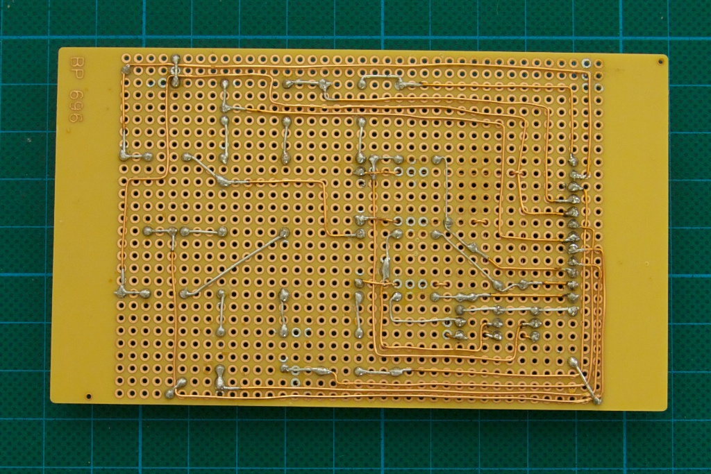
In the second post about the tiny 3x3x3 cube I want to present the second board which I made (actually my girlfriend made the first one). This board features a more advanced design than all the previous ones.
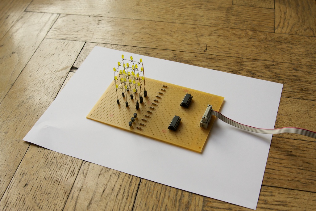

The main difference to the other boards is that this one uses shift registers to switch the LEDs on and off. This reduces the wires that are necessary to connect the board to the Arduino. There are only 6 wires needed, two for Vcc and GND and the other four for programming the shift registers. The board from part one needed 13 wires.
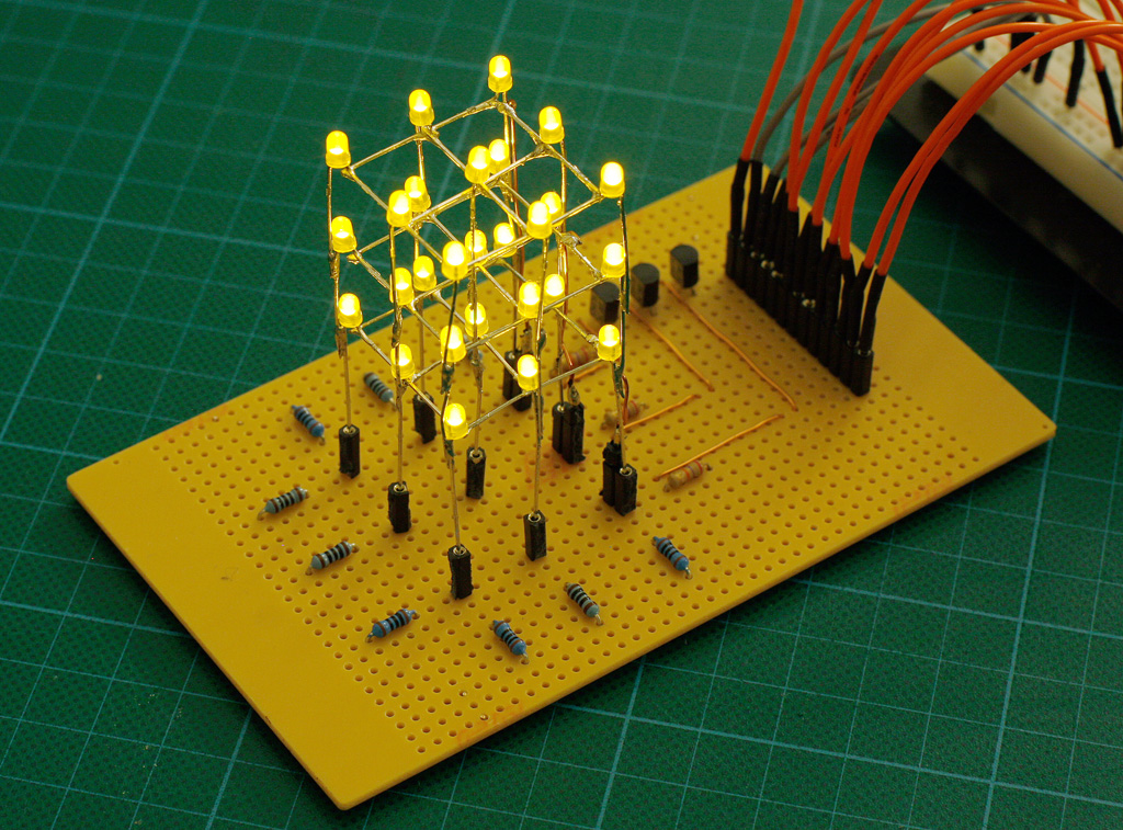
The design is based almost entirely on this tutorial from the Arduino website: http://www.arduino.cc/en/Tutorial/ShiftOut This is well explained that it doesn’t need any more words from my side. The big advantage of using shift registers is that no more wires are necessary even if more registers are added to address more LEDs. While this approach seems to be alright it has one drawback on my board. The shift registers I used can only source 70mA of current. I mentioned in the previous post that if all LEDs on one layer are on at the same time, they use up to 180mA. That is more than twice of what the shift register can deliver. That means that when an entire horizontal layer is on, the LEDs are a lot darker as each of them only gets 7,77mA.
Even though this board is more sophisticated it is still trivial to make, if you follow my posts about building the cube and the Arduino tutorial about using the shift registers. Still this is only one more step and these boards and cubes are almost one year old. I knew a lot less back then and you can see that. I wanted to write about them anyway, since they work in some way and help to explain certain concepts.
The next posts will be about my current efforts. New LEDs, new cubes, new chips etc. I even bought an FPGA board for building a large cube so there is a lot more in the pipeline here. I hope the next post will be on my new blog though. I had so many troubles with tumblr recently that I’m frustrated enough to move away from it. Temporarily I will host a wordpress blog myself. Later on I will write my own basic blog software as wordpress is just to bloated. Compared to tumblr, a self hosted wordpress is at least accessible and offers features which tumblr and other sites just don’t offer.
I’ll let you know when the new blog is ready. In the meantime I will post a video and the code for the cube … as tumblr is really annoying when you want embed videos in text posts *sigh*
3x3x3 LED Cube – Part #1
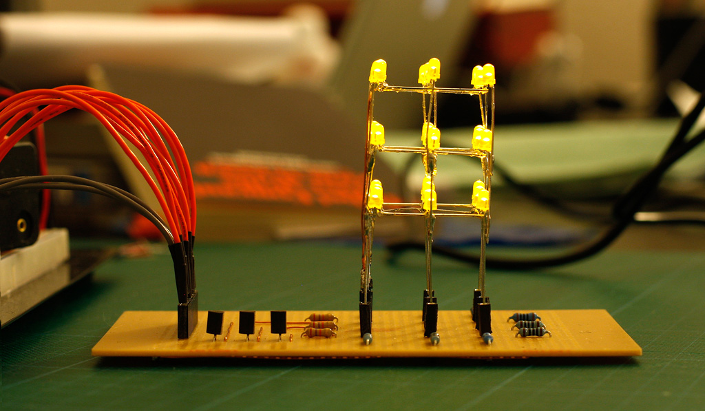
Until now I haven’t posted any schematics. This is because the cubes I’ve shown so far were too trivial. This also the case with this 3x3x3 LED cube and its board. As you can see it uses a lot of wires. 9 Wires for addressing the LEDs on a layer, 3 more wires for multiplexing / switching the layers and one more wire for GND. The Arduino Board provides enough pins and so no fancy techniques are necessary yet. While the board looks clean and simple on the top, the actual wiring on the bottom is a little more complicated.
Even a 3x3x3 cube involves some work. The only new concept here is the use of transistors for switching the layers.
Power
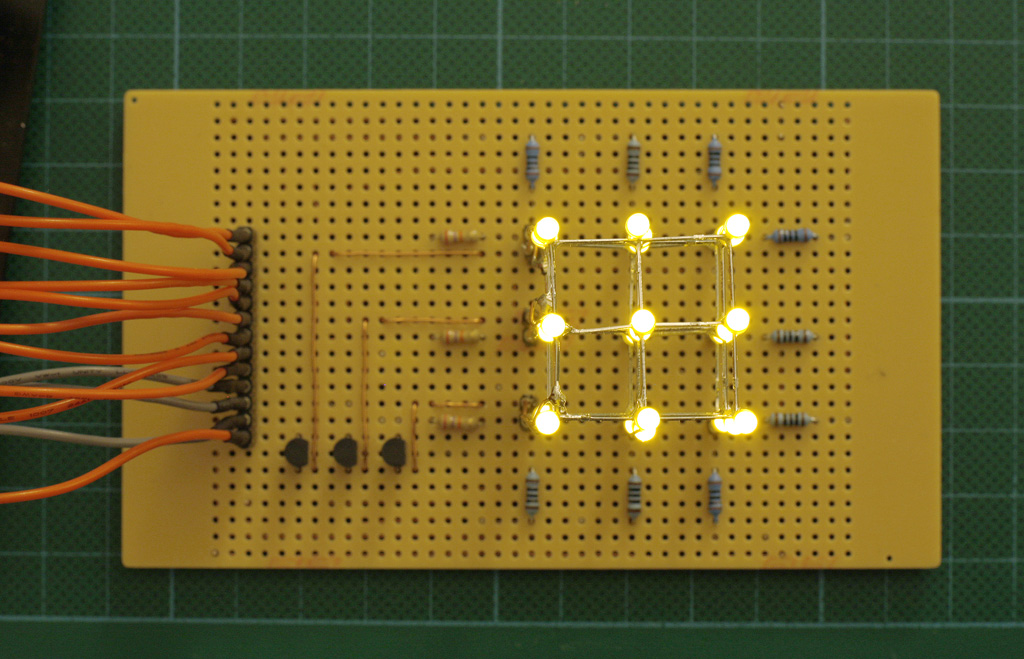
This cube has common cathode layers and common anode columns. This is because each column is directly connected to one of the Arduino IO pins. These pins can provide a current up to 40mA. A typical LED needs around 20mA for full brightness and since there is only one layer connected to GND (-) at the same time each column only draws 20mA at any given time.
The layers are connected to transistors which allows switching the layers to GND with three IO pins. The transistors are all connected to a common GND which has the advantage of requiring only one GND wire instead of having individual wires to for each transistor.
Also notice that all the LEDs are connected via the cathode which means that if an entire layer is lid up at once, a 180mA (9 * 20mA) are flowing through the transistor.
I don’t have the code for running the cube on that board anymore but I build a second board with shift registers which I will show in the next post.